lucy@zlwyindustry.com
+86-158-1688-2025
Please Choose Your Language
- All
- Product Name
- Product Keyword
- Product Model
- Product Summary
- Product Description
- Multi Field Search

Views: 0 Author: Site Editor Publish Time: 2026-08-01 Origin: Site


Industrial heating systems harbor immense energy potential. Unlocking this power safely requires absolute precision and rigorous control logic. A standardized burner sequence of operation serves as the foundational safeguard for any boiler, furnace, or thermal processing unit. Far beyond a simple mechanical checklist, it dictates the exact, non-negotiable steps a Burner Management System (BMS) must execute. Without strict adherence to this logic, facilities risk unignited fuel accumulation. They also face severe structural damage and catastrophic combustion anomalies. For facility engineers and procurement teams evaluating system upgrades, understanding this process is absolutely critical. We will explore everything from the initial call for heat through the final purge stages. You will discover how these protocols guarantee operational uptime. They also maintain strict compliance with rigorous safety standards like EN 746-2 and NFPA 85.
The financial and operational stakes of combustion safety are immense. When a control system fails to execute correctly, the consequences ripple across the entire facility. We must understand the core reasons driving these strict protocols.
Incomplete air sweeps leave volatile residual gases inside the chamber. Delayed flame detection causes unburned fuel pooling. These specific scenarios trigger explosive "hard starts." A hard start generates massive pressure waves inside the boiler. These waves crack refractory bricks and damage burner heads. Repeated anomalies force costly equipment lockouts. They halt production lines unexpectedly. We simply cannot afford these sudden operational disruptions. Reliable sequencing prevents these destructive events entirely.
The logic behind a burner start sequence is never a proprietary preference. It represents a strict, legally binding regulatory requirement. Facility managers must adhere to established industry frameworks. For example, EN 746-2 dictates stringent requirements for handling gaseous fuels. Likewise, marine boilers operate under strict United States Coast Guard (USCG) control guidelines. NFPA 85 outlines specific interlock requirements for multiple burner systems. You must follow these codes to pass municipal inspections. Compliance ensures baseline facility safety and satisfies insurance mandates.
Precise, repeatable sequencing directly impacts long-term equipment health. It prevents sudden thermal shock inside the delicate combustion chamber. It reduces unnecessary electrical wear on ignition transformers. It also minimizes unplanned maintenance outages. Stable sequences keep your operation running smoothly over the long term. Predictable startups extend the lifespan of every internal component.
Common Mistake: Many operators assume generic control settings work safely for all burner sizes. This is dangerously incorrect. Code compliance requires precise tuning. You must base purge timers on specific equipment volumes and flue lengths.
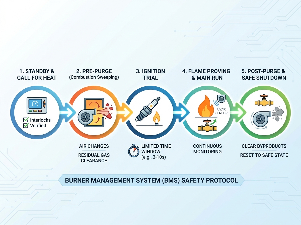
Every safe combustion event follows a highly structured timeline. The BMS monitors specific parameters at each stage. It aborts the cycle if any parameter falls outside safe limits.
The process begins quietly. The system thermostat or process controller signals a demand for heat. The BMS springs into action immediately. It first verifies all critical safety interlocks are fully satisfied. It checks internal water levels. It confirms optimal gas pressure switches. It also monitors draft limits. If any single interlock fails, the system halts. It will not proceed until you resolve the physical fault.
Next comes the highly critical pre-purge phase. The main combustion blower activates immediately. It forces a calculated volume of fresh air through the entire system. This air travels through the combustion chamber and exits the flue passages. This action clears any unburned combustible gases. It removes vaporized liquids from previous cycles.
Evaluation Note: Look for programmable purge timers. You need a minimum of four complete air changes to guarantee a safe ignition environment. Some marine applications require up to eight air changes.
The system then enters the ignition trial. The high-voltage ignition transformer energizes. The pilot or primary gas valve opens simultaneously. This creates a spark gap to ignite the initial fuel mixture. This specific time window is intentionally restricted. It usually lasts only 3 to 10 seconds to mitigate risk. If the optical sensors do not confirm ignition, the system reacts instantly. It triggers an immediate, hard safety shutdown.
Once ignited successfully, flame proving takes over the monitoring duties. Optical sensors (like UV or IR scanners) confirm the presence of a stable flame. Some systems use physical flame rods relying on ionization. Only upon positive verification does the main fuel valve open fully. Emphasize this critical point to your operators. Flame proving is never a one-time step. It remains a continuous, unyielding requirement throughout the entire run cycle.
Eventually, the system satisfies the original heat demand. The main fuel valves snap closed immediately. However, the combustion blower continues to run. This marks the post-purge phase. It sweeps residual combustion byproducts out of the chamber. It actively cools the burner head. Finally, it resets the internal environment for the next safe standby phase.
Burner Sequence Phase Summary
| Phase | Primary Action | Safety Function | Typical Duration |
|---|---|---|---|
| Standby | Interlock verification | Prevents unsafe startup | Varies (until heat call) |
| Pre-Purge | Blower activates at high speed | Clears volatile residual gases | Based on 4-8 air changes |
| Ignition Trial | Spark and pilot fuel engage | Establishes initial pilot flame | 3 to 10 seconds max |
| Flame Proving | Sensors continuously monitor flame | Prevents raw fuel pooling | Continuous during operation |
| Post-Purge | Blower runs after fuel off | Clears combustion byproducts | 15 to 60 seconds |
Procuring a new BMS requires careful technical evaluation. You must look beyond basic functionality. You must prioritize diagnostic depth, component redundancy, and communication protocols.
The combustion industry has shifted permanently away from legacy mechanical relays. Older relays frequently stick open. This causes catastrophic sequencing failures. Today, we rely exclusively on modern microprocessor-based controls. These digital units prevent operators from bypassing sequence steps. They enforce hardcoded safety limits continuously. They provide a tamper-proof barrier against manual overrides.
When evaluating a BMS upgrade, thoroughly examine its diagnostic capabilities. Can the controller specify exactly where a failure occurred? A digital log reading "Lockout: Failed Ignition Trial" is highly valuable. A generic red "Fault" light is virtually useless. Specific fault annunciation drastically reduces your Mean Time to Repair (MTTR). Technicians can pinpoint issues immediately instead of guessing.
Consider how the burner control system communicates outward. Modern systems send sequence states directly to central monitoring panels. They utilize industrial protocols like Modbus or PROFINET. SCADA integration allows facility managers to track performance trends easily. You can monitor flame signal strength over time. You can implement predictive maintenance before a sudden shutdown occurs.
High-capacity industrial applications require robust, redundant hardware. Component redundancy is an absolute necessity, not an optional luxury. Ensure your system utilizes dual safety shutoff valves. Install proper vent limiters on gas trains. Use redundant flame scanners to cross-verify signals on large utility boilers. Redundancy ensures one failed component never causes an explosion.
Best Practices for BMS Evaluation:
Even the most advanced systems encounter operational hiccups. Understanding common failure points helps maintenance teams restore operational status swiftly and safely.
Many systems fail before they even start. Common roadblocks prevent the sequence from initiating entirely. Malfunctioning combustion air pressure switches are frequent culprits. They fail to detect the blower airflow. Blocked vent lines also cause immediate gas pressure interlock failures. Low water cutoffs frequently trip due to minor scale buildup. You must verify these physical constraints first before suspecting the digital controller.
Sensor degradation causes major operational headaches. Soot accumulation on UV scanners physically blinds the sensor. Worn flame rods lose electrical conductivity over time due to extreme heat. These minor issues trigger frustrating false flame failures. The system drops the load unexpectedly. Regular cleaning and scheduled calibration prevent these nuisance lockouts.
Never alter purge timers manually without professional recalculation. Modifying timers to speed up production is extremely dangerous. It violates fundamental safety codes. If you change burner capacities, you alter the combustion dynamics. If you modify exhaust flue lengths, you alter the system volume. You must recalibrate the timers professionally to maintain the required four air changes.
Troubleshooting Sequence Failures:
Upgrading a legacy burner system requires a methodical approach. You must audit your current capabilities, demand vendor transparency, and execute rigorous physical testing.
Start by comprehensively evaluating your current setup. Does your legacy system meet modern sequencing codes? Many older panels lack fail-safe digital logic entirely. They often require complete retrofitting to comply with current NFPA standards. Document every existing interlock switch. Map out your current timer settings. Identify any outdated mechanical relays prone to sticking.
Demand absolute transparency from control system manufacturers. They must provide verifiable documentation of code compliance. Look specifically for UL, CE, or FM approvals on the spec sheets. Request clear sequence-of-operation flowcharts before purchasing. You need to understand their exact logic pathways visually. Reject vendors who obscure their safety logic behind proprietary black boxes.
Successful implementation requires rigorous physical testing. You must execute a comprehensive Site Acceptance Test (SAT). Test the sequence actively under simulated fault conditions. For example, intentionally blind the flame scanner during operation. Verify the fuel valves shut down within the required timeframe. Drop the gas pressure manually to ensure the low-pressure switch aborts the startup. Document every successful test to satisfy insurance auditors.
Strict adherence to operational sequencing forms the ultimate barrier against critical system failure. Every phase protects your facility from unstable combustion and catastrophic pressure events. By understanding the core logic behind these steps, facilities can maintain a safer, more efficient operational footprint.
Facility decision-makers should take immediate action based on these principles. Review your current BMS diagnostic logs to identify recurring nuisance lockouts. Verify your existing sequence timers against updated compliance standards like NFPA 85 or EN 746-2. Audit your physical interlocks and redundant safety valves for proper mechanical operation. Finally, consult with specialized combustion engineers to scope necessary digital control upgrades for outdated systems.
A: Pre-purge occurs before ignition to clear any unburned fuel that may have leaked during standby, preventing explosive starts. Post-purge occurs immediately after the fuel valves close to sweep combustion byproducts from the chamber before the next cycle.
A: The duration is not arbitrary; it is calculated based on the volume of the combustion chamber and flue. Safety standards generally require enough time to complete at least four to eight full air changes.
A: The burner management system will instantly close the fuel valves to prevent fuel pooling, initiate a post-purge to clear the hazardous mixture, and enter a hard "lockout" state that requires manual operator reset and investigation.
A: This usually indicates a failure in the proving interlocks. Common culprits include a defective combustion air proving switch, low blower motor speed, or a failure in the draft limit switch, preventing the controller from safely advancing to ignition.