lucy@zlwyindustry.com
+86-158-1688-2025
Please Choose Your Language
- All
- Product Name
- Product Keyword
- Product Model
- Product Summary
- Product Description
- Multi Field Search

Views: 0 Author: Site Editor Publish Time: 2026-08-15 Origin: Site


Unstable gas delivery seriously compromises process repeatability across industrial operations. It damages sensitive downstream instrumentation. It also creates severe, unacceptable safety liabilities in your facility. Engineers frequently conflate normal regulator mechanical behaviors—specifically droop and lock-up—with critical component failures like creep. Misdiagnosing these complex phenomena directly leads to improper specification. You might over-size your components. Alternatively, you might entirely ignore critical fluid system vulnerabilities. When you misunderstand these pressure dynamics, you risk shutting down operations unnecessarily. You might also replace perfectly functional hardware.
This article provides a clear, engineering-grade framework. It helps you navigate these distinct concepts. We will show you exactly how to distinguish, measure, and mitigate gas regulator droop lock-up creep effectively. By mastering these core principles, you can confidently evaluate your systems. You will learn to specify the exact pressure control solutions needed for your facility.
No mechanical regulator maintains a perfectly flat flow curve. Operational realities dictate some fluctuation based on flow rates. Supply pressure changes also play a massive role. The internal forces constantly balance against each other. To achieve true outlet pressure stability, you must understand how these internal components interact.
We must cleanly distinguish the three main phenomena governing pressure changes. They operate under entirely different conditions. They require vastly different engineering responses.
You must apply a strict evaluation lens. Understanding the difference between a functional limitation and a component failure dictates your next steps. A functional limitation like droop requires a design upgrade. A component failure like creep demands immediate maintenance.
| Phenomenon | Operational State | Nature of the Issue | Recommended Action |
|---|---|---|---|
| Droop | Active Flow | Expected mechanical limitation | Optimize Cv / Upgrade to dome-loaded |
| Lock-Up | Transition to No-Flow | Normal sealing requirement | Verify downstream component tolerances |
| Creep | Static No-Flow | Critical seal failure | Immediate component replacement |
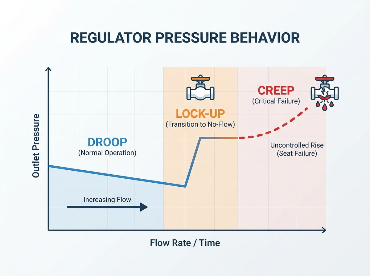
When analyzing regulator droop, we look closely at the underlying physics. As gas flow increases, the internal sensing element moves. The diaphragm or piston physically shifts away from the seat. This movement allows the loading spring to expand. When the spring expands, it loses its original compressive force. This mechanical relaxation causes a corresponding drop in your fluid line pressure.
The business impact of this phenomenon is severe. Excessive drop leads to gas starvation at critical usage points. Starved processes trigger sudden system alarms. Manufacturing quality becomes highly inconsistent. You might experience unplanned process shutdowns. Engineers must actively combat this physical limitation.
You can effectively manage these variations using several proven strategies. Implementation depends entirely on your process sensitivity.
Common Mistake: Do not just increase the set pressure to compensate for droop under high flow. When the flow suddenly stops, the pressure will spike aggressively. This spike can damage your sensitive equipment.
We must clearly define the mechanics behind shutting off a gas stream. To completely halt gas flow, the sensing element must generate massive force. It needs to press the poppet firmly against the seat. This action effectively creates a tight mechanical seal.
To generate this force, the system requires a slight pressure build-up. It must rise slightly above your original flowing setpoint. This expected increase represents normal lock-up pressure. Every mechanical design exhibits this trait.
Sometimes, this sealing pressure spikes higher than acceptable limits. Several mechanical factors drive these excessive spikes.
System design considerations are absolutely paramount here. Your downstream piping must handle this maximum anticipated pressure. Gauges and sensitive analytical equipment require specific ratings. If the closing force exceeds downstream component tolerances, you face a major risk. Secondary pressure relief valves (PRVs) become a mandatory compliance addition. They protect your expensive instruments from sudden spikes.
You must never confuse the initial sealing spike with continuous leakage. Unlike lock-up, which stabilizes at a specific elevated pressure, regulator creep is an uncontrolled failure. It causes a continuous, creeping rise in outlet pressure. This only happens when downstream valves are entirely closed.
This steady climb indicates a fundamental breakdown. The gas is actively bypassing the main seat. It seeks to equalize the upstream and downstream zones.
Understanding why seats fail helps you implement better preventative measures. Seats endure harsh environments. They degrade over time through multiple vectors.
The safety and compliance risks are staggering. Left unchecked, this slow leak will completely equalize upstream and downstream pressures. Full cylinder pressure can suddenly hit low-pressure lines. This catastrophic event can rupture downstream tubing. It easily destroys delicate instruments. In worst-case scenarios, it results in hazardous gas release into the workspace.
Best Practice: Implement strict risk mitigation protocols immediately. You need mandatory installation of upstream inline particulate filters. Filters capture debris before it damages the soft seat. Furthermore, establish routine preventative maintenance cycles. Do not wait for failure. Schedule regular seat and O-ring replacements based on verified operational lifecycles.
Aligning your hardware architecture with your process requirements requires careful evaluation. You must analyze the feature-to-outcome relationship. Proper specification prevents instability before it starts.
Consider these architectural choices carefully:
Your shortlisting logic should rely on hard data. Base your procurement decisions strictly on verified manufacturer flow curves. Analyze the required turn-down ratios (rangeability). Investigate available upstream filtration options. Never base your purchase solely on pipe size or maximum pressure ratings. Evaluating the entire fluid system yields much better operational results.
Mastering gas regulator droop lock-up creep distinctions prevents costly over-engineering. It effectively protects your facility against dangerous system failures. You now understand the physics driving flow curves. You can distinguish between a functional spring limitation and a catastrophic seal failure.
Your next steps require immediate action. Audit your current fluid systems thoroughly. Review your manufacturer flow curves against your actual pressure decay data. Consult with a certified fluid system specialist. They can help determine if your ongoing instability is merely a sizing issue or a dangerous contamination issue. Proactive evaluation ensures your systems remain safe, compliant, and highly efficient.
A: Regulator droop is the loss of outlet pressure due to an increase in downstream flow demand. Supply pressure effect (SPE) is a change in outlet pressure caused by a fluctuation in the upstream supply pressure (e.g., a gas cylinder emptying).
A: Close the downstream valve to stop flow completely. Note the pressure rise for lock-up. If the pressure gauge stabilizes, it is operating normally. If the pressure continues to slowly climb toward the upstream pressure level over several minutes or hours, the regulator is experiencing creep.
A: No mechanical regulator is completely immune to droop, but dome-loaded regulators replace the mechanical spring with a compressible gas volume. This drastically reduces the physical variations that cause droop, resulting in a significantly flatter flow curve and highly stable outlet pressure.
A: Not necessarily. While excessive lock-up can indicate internal friction or oversizing, every regulator requires a designated lock-up zone to seal. Consult the manufacturer's technical specifications to determine the acceptable lock-up range for your specific model.