lucy@zlwyindustry.com
+86-158-1688-2025
Please Choose Your Language
- All
- Product Name
- Product Keyword
- Product Model
- Product Summary
- Product Description
- Multi Field Search

Views: 0 Author: Site Editor Publish Time: 2026-07-26 Origin: Site


Inaccurate equipment specifications bring serious operational risks. Facilities frequently face short-cycling, massive fuel waste, elevated emissions, and localized furnace overheating. Sizing standard single-fuel systems presents minimal hurdles. However, dual-fuel applications introduce severe complexities. Switching between gaseous and liquid fuels changes flow dynamics and combustion characteristics instantly. Engineers must account for drastically different thermal behaviors across multiple operating modes.
This guide provides a reliable framework for calculating required thermal capacity. We will help you evaluate low-fire performance metrics accurately. You will learn to align equipment specifications directly to your daily operational realities. Proper sizing fundamentally dictates your facility's long-term energy footprint. Mastering these formulas protects equipment lifespan. It also prevents environmental compliance violations during winter fuel transitions. We aim to equip you for smarter, data-driven upgrade decisions.
Establishing an accurate operational baseline prevents catastrophic equipment mismatch. You must evaluate exact thermal demand before analyzing specific combustion hardware. Different applications require vastly different sizing methodologies.
A crucial first step involves distinguishing steady-state steam generation from highly variable direct-fired applications. Establishing the proper boiler burner capacity requires analyzing continuous steam usage patterns. Boiler loads typically supply building heat or steady manufacturing processes. They demand consistent, stable energy delivery over long operational shifts.
Conversely, a direct process heating load fluctuates wildly. Batch processing, industrial drying, and metal smelting introduce rapid thermal spikes. These applications pull massive amounts of energy instantly. They also drop to minimal demand just as quickly. You must track these usage curves across full production cycles.
You cannot size combustion equipment for extreme transient spikes. Doing so guarantees severe oversizing. Brief surges lasting only seconds or minutes distort your actual demand profile. Instead, engineers must calculate the highest sustained peak. We define a sustained peak as the maximum load holding steady for at least fifteen minutes. This metric ensures the system meets heavy production needs safely.
Manufacturers rate boilers based on their thermal output. However, combustion equipment runs based on thermal input. You must convert your required output into an accurate input requirement. The standard industry formula dictates dividing required boiler output by anticipated efficiency.
For example, you need 10,000,000 BTU/hr of steam output. You operate an older firetube boiler. Do not assume 100% efficiency. Nameplate efficiency rarely translates to real-world performance. You should assume a realistic baseline efficiency of 80% to 85% for older units. Dividing 10,000,000 by 0.80 yields a required burner input of 12,500,000 BTU/hr. Using optimistic efficiency assumptions leaves your facility fundamentally underpowered during peak winter operations.
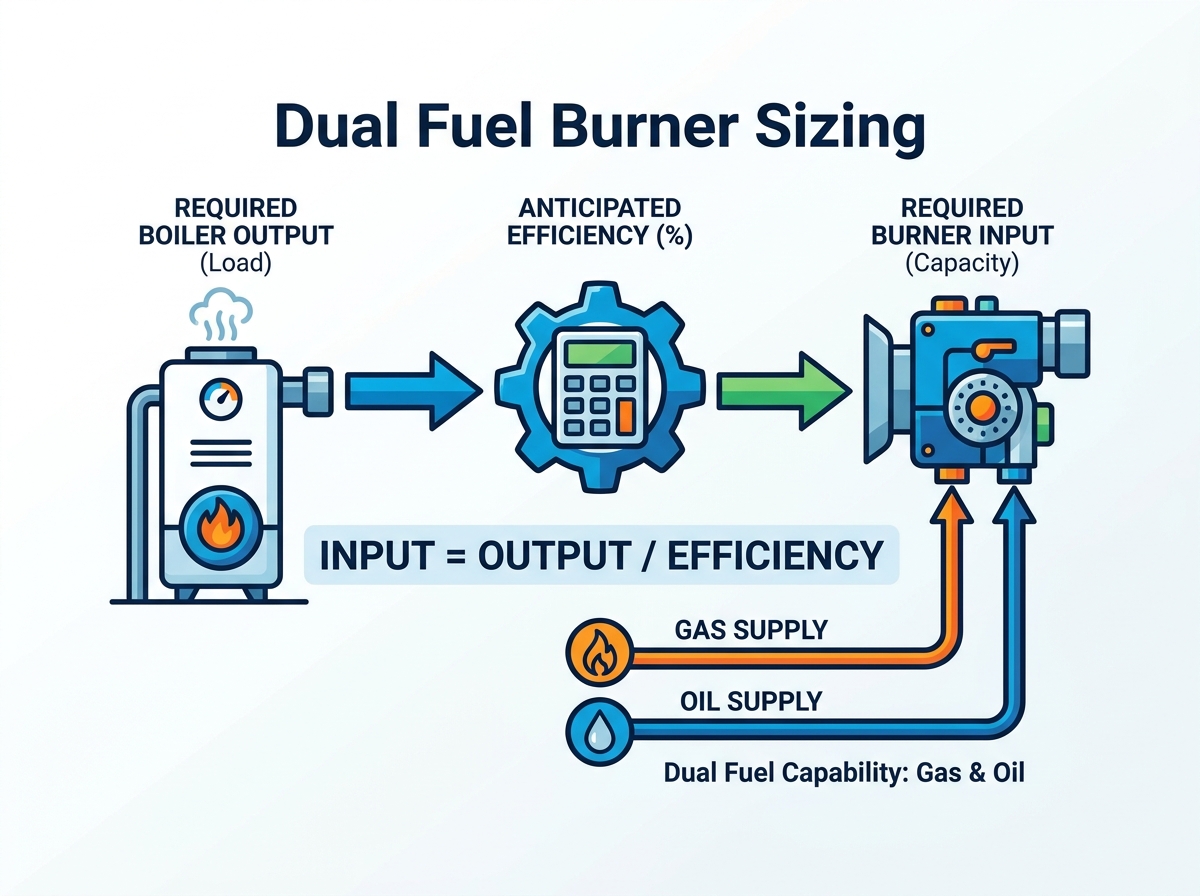
Theoretical math must translate into real-world physics. Accurate dual fuel burner sizing requires adjusting base input numbers for site-specific environmental factors. Neglecting these corrections ruins combustion performance.
Site elevation aggressively derates combustion capacity. Air density decreases as altitude increases. Less dense air contains fewer oxygen molecules per cubic foot. The blower motor must push significantly higher volumes of air to maintain proper fuel-to-air ratios. Industry standards dictate a roughly 4% capacity loss per 1,000 feet of elevation above sea level. Ambient air temperature variations also affect oxygen density. Facilities operating in high-altitude, high-heat environments face compounding capacity penalties.
The following chart illustrates standard altitude derating factors for combustion systems.
| Site Elevation (Feet) | Estimated Capacity Loss (%) | Required Multiplier for Sizing |
|---|---|---|
| Sea Level (0) | 0% | 1.00 |
| 1,000 | 4% | 1.04 |
| 2,000 | 8% | 1.08 |
| 3,000 | 12% | 1.12 |
| 4,000 | 16% | 1.16 |
| 5,000 | 20% | 1.20 |
Equipment benches test beautifully in open air. Real boilers restrict airflow entirely differently. The specific aerodynamic resistance inside your heat exchanger creates furnace backpressure. Higher backpressure limits actual thermal delivery. Firetube designs, water-tube configurations, and complex economizer additions all increase static pressure. You must source the manufacturer's performance curve. Then, cross-reference your calculated input requirement against your specific furnace backpressure limit. A blower fan sized too small cannot overcome boiler resistance, causing dangerous fuel-rich conditions.
Piping configurations introduce minor friction losses. Refractory degrades over time. Wear and tear subtly reduce mechanical efficiency. Adding a sensible safety margin protects your operation. We recommend a strict 10% to 15% tolerance above the fully corrected maximum load. This cushion handles unforeseen production bumps perfectly.
However, you must avoid arbitrary padding. Engineers sometimes add 30% or 40% margins out of fear. This practice destroys low-fire stability. It guarantees the equipment will operate poorly during mild weather conditions.
Managing two distinct energy sources requires dual mathematics. Accurate gas oil burner sizing forces you to accommodate contradictory flow characteristics. Natural gas flows via pressure gradients. Liquid oil requires aggressive atomization.
You cannot assume standard heating values. You must verify the Higher Heating Value (HHV) of your specific natural gas supply. Local utilities often deliver gas blends featuring fluctuating thermal contents. Backup fuel presents greater challenges. Number 2 Light Oil burns entirely differently from Number 6 Heavy Oil. Heavy oils demand pre-heating systems to reduce viscosity before atomization. Failing to calculate the exact calorific value of both your primary and backup fuels results in mismatched valve sizing.
Delivery mechanisms vary drastically between fuels. Gas valve trains rely on dynamic pressure drops. If your facility receives 2 PSI of incoming natural gas pressure, the main regulating valves, safety shutoffs, and butterfly valves will consume a portion of this pressure. You must size the gas train to ensure adequate pressure reaches the firing head. Oil delivery relies on mechanical pump pressure. High-pressure atomization loops often require 100 to 300 PSI. The respective delivery networks demand independent sizing calculations.
Firing modes dictate differing emissions profiles. Burning liquid fuels generates higher nitrogen oxide (NOx) and particulate matter levels. To maintain compliance, systems utilize Flue Gas Recirculation (FGR) or increase excess air ratios. Introducing heavy FGR alters flame geometry and volumetric airflow requirements. You must ensure the blower housing and impeller can support the increased mass flow required when firing backup oil under strict environmental permits.
Peak load capacity guarantees you meet extreme demands. Low-fire capability guarantees you save money every other day of the year. You must evaluate the minimum firing rate carefully.
Turndown measures the ratio between maximum and minimum firing rates. A 10:1 ratio means a 10,000,000 BTU/hr system modulates down to 1,000,000 BTU/hr. Achieving identical turndown across different fuels remains mechanically difficult. Standard setups might offer 10:1 on natural gas but only 8:1 on light oil. Liquid fuels face atomization limits. If you slow the oil flow too drastically, the spray droplets become too large. Large droplets fail to burn completely, creating soot and unburned hydrocarbons.
Maximizing burner turndown directly prevents short-cycling. Short-cycling occurs when the minimum firing rate exceeds the actual system demand. The equipment overheats the water rapidly, shuts off, and initiates a mandatory pre-purge sequence. This purge blasts cold ambient air through the hot boiler. Purging wastes massive amounts of stored thermal energy. A wider operating range allows the equipment to modulate continuously. Continuous modulation reduces mechanical wear on linkages, ignition transformers, and blower motors.
You must align the minimum firing capability to your facility's lowest anticipated off-peak load. Imagine a manufacturing plant operating heavily during weekdays but maintaining minimal building heat over weekends. The weekend heat load represents your absolute minimum floor. If the weekend load sits at 2,000,000 BTU/hr, your equipment must cleanly dial down to match it. Failing to verify this floor ensures constant weekend short-cycling.
Theoretical calculations often look perfect on paper. Physical installation realities frequently ruin those perfect models. You must anticipate mechanical integration barriers early in the design phase.
Over-engineering capacity ruins thermal performance. When engineers oversize equipment, the turndown ratio essentially shrinks in practical application. A massive blower fan pushing minimal air at low fire becomes unstable. Airflow loses its velocity. Flame stability degrades instantly. An oversized unit struggles to meet strict NOx guarantees at minimum fire because the mixing dynamics fail. Additionally, oversized modulation motors constantly hunt for proper positions, increasing mechanical failure rates.
Thermal numbers tell only half the story. The physical blast tube must clear the existing boiler door opening. More importantly, the resulting flame shape must fit the combustion chamber. Long, narrow flames suit certain firetube boilers. Short, bushy flames work better for specific water-tube configurations. If an oversized flame impinges on refractory material or cold water walls, it quenches prematurely. Flame impingement creates immediate carbon monoxide spikes and destroys boiler steel over time.
Pairing advanced combustion hardware with legacy controls negates efficiency gains. Single-point positioning systems use mechanical linkages to tie the fuel valve and air damper together. These mechanical rods bend and wear over time, introducing hysteresis. Modern parallel positioning uses dedicated servo motors for each fuel valve and air damper. These servos communicate digitally.
Here are common mistakes engineers make during implementation:
Approaching vendors without strict data guarantees suboptimal proposals. You must control the narrative by providing precise engineering parameters. Vendors rely on clear inputs to guarantee operational performance.
Gather hard data before initiating vendor outreach. You need your exact maximum steam or hot water requirements mapped against your lowest operational demand. Document the exact physical dimensions of your combustion chamber. Measure the blast tube insertion depth. Compile your local emissions limits for both primary gas and backup oil. Finally, confirm your exact incoming dynamic gas pressure under full load conditions.
Do not accept generic performance brochures. Ask targeted technical questions. Challenge manufacturers to prove their claims under your specific operational conditions.
Focus your decision framework entirely on long-term efficiency returns. Advanced combustion heads command higher initial purchase prices. Parallel positioning servos increase upfront hardware expenses. However, these technologies eliminate purge cycle heat loss. They lower baseline oxygen levels safely. They prevent short-cycling during low-demand periods. The resulting monthly fuel savings routinely offset higher initial purchase prices within the first two heating seasons. Prioritizing cheap hardware guarantees higher lifetime fuel consumption.
Precision sizing fundamentally dictates equipment longevity and fuel economy. Guessing at peak loads or applying arbitrary safety margins guarantees poor combustion stability. You must accurately calculate heat input, verify fuel-specific delivery pressures, and account for site elevation.
Furthermore, evaluating low-fire capabilities proves just as important as meeting peak demand. High turndown ratios protect your boiler from thermal shock and eliminate wasteful purge cycles. Hardware integration demands exact dimensional matching and modern parallel positioning controls.
Consolidate your site's load profile data, specific elevation metrics, and exact fuel characteristics today. Stop relying on outdated boiler nameplates. Engage an application engineer to run a site-specific combustion analysis before ordering any replacement hardware.
A: Boiler capacity focuses on indirect heating via steam or hot water over steady operational shifts. Process capacity deals with direct thermal integration for specific manufacturing actions, like industrial drying or smelting. Process loads feature rapid, extreme thermal spikes, requiring highly responsive modulation controls compared to steady-state boilers.
A: Altitude decreases ambient air density. Less dense air contains less oxygen per cubic foot. The blower motor must push significantly higher volumes of air to achieve proper combustion. Engineers generally expect a 4% capacity derating for every 1,000 feet above sea level, necessitating larger blower fans.
A: Yes, this represents standard physics. Natural gas flows easily and allows highly precise pressure regulation, often achieving 10:1 turndown. Liquid oil relies on mechanical atomization. If oil flow drops too low, spray droplets become too large to burn cleanly. This limits standard oil turndown to roughly 8:1.
A: Oversizing triggers frequent short-cycling. The system rapidly meets demand, shuts off, and purges ambient air through the boiler, wasting massive amounts of heat. Oversizing also degrades flame stability at low fire, increases mechanical wear on servos, and causes severe thermal shock to internal boiler components.