lucy@zlwyindustry.com
+86-158-1688-2025
Please Choose Your Language
- All
- Product Name
- Product Keyword
- Product Model
- Product Summary
- Product Description
- Multi Field Search

Views: 0 Author: Site Editor Publish Time: 2026-08-02 Origin: Site


Reliable burner safety interlocks are never just simple regulatory hurdles to clear. They form the absolute baseline for facility safety, asset longevity, and minimizing unplanned downtime in your plant. Right now, facility engineers and safety managers face critical upgrade decisions. You must evaluate transitions from legacy relay-based systems to modern Burner Management Systems (BMS). Aging equipment often causes costly nuisance trips. It creates operational blind spots during critical firing phases. Upgrading these systems ensures you maintain highly competitive and safe industrial operations. Modern controllers transition seamlessly from basic fault-catching to proactive proving. They offer advanced diagnostics to keep your plant running smoothly. You will learn exactly how modern logic sequences manage physical interlock chains. We will explore combustion air verification, fuel delivery safeguards, and continuous monitoring. Finally, we will outline best practices for selecting the right controller to protect your facility effectively.
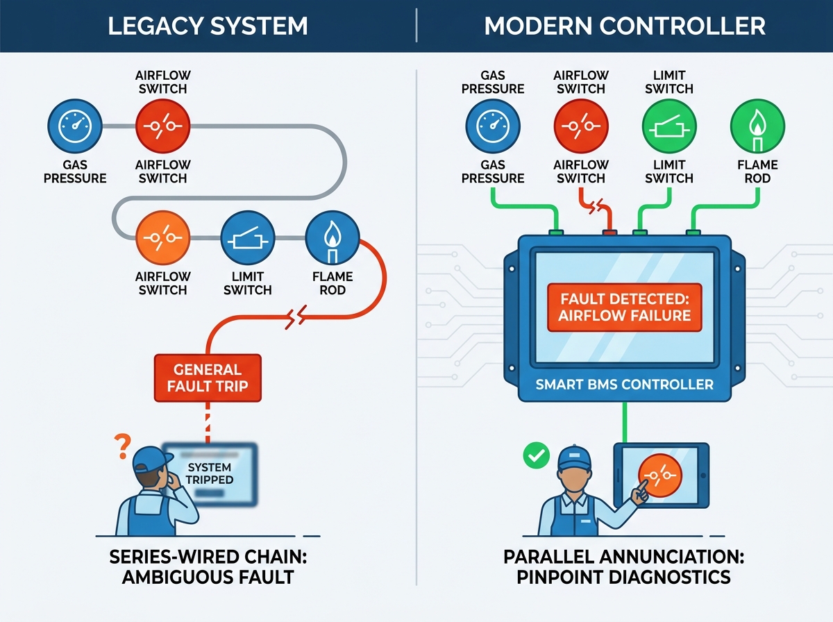
Legacy series-wired interlock chains carry enormous hidden costs. They create massive frustration through "first-out" fault ambiguity. Imagine walking into a boiler room after an unexpected shutdown. The entire firing sequence has tripped. You look at the control panel. It only displays a generic fault light. Did a pressure limit switch trip? Did the forced draft fan fail? A legacy series circuit will never tell you. You must test every single relay manually. This extended diagnostic downtime ruins production schedules. It forces maintenance teams into stressful, reactive troubleshooting.
We must also address the reality of industrial compliance. Meeting minimum NFPA 85 or EN 746-2 standards is a legal necessity. However, baseline compliance does not inherently guarantee operational efficiency. Standard codes dictate what safety conditions you must protect against. They do not dictate how quickly your system should diagnose a fault. Many facilities remain compliant while suffering terrible operational efficiency.
You need clear success criteria for evaluating a modern BMS. A successful upgrade achieves zero compromise on facility safety. Simultaneously, you gain granular visibility into your process. You want immediate, plain-text alerts showing the exact cause of any burner trip. This modernization transforms a blind safety loop into an intelligent diagnostic asset.
Controllers rely on physical field devices to verify safe conditions. We break these field devices down into three core solution categories.
Burners require precise air volumes to achieve safe, stable combustion. Industrial controllers manage this through physical airflow proving switches. These mechanisms measure differential air pressure across a physical restriction. They capture actual air movement inside the ductwork.
Modern logic demands verification before and during the purge cycle. Controllers also monitor airflow continuously during the main firing sequence. You cannot rely on assumed fan motor states. Motor contactors might close, but fan belts break. Filter intakes easily clog. A smart controller demands physical pressure verification to prevent explosive gas accumulations.
Fuel systems present the highest volatility in any thermal process. The high and low gas pressure switch acts as the primary defense line. High pressure indicates a failed upstream regulator. Low pressure indicates insufficient fuel for a stable flame core. Both conditions demand an immediate, hard shutdown.
Facilities must evaluate dual-valve blocking and bleed systems carefully. These systems use two shutoff valves separated by a vent valve. When the burner shuts down, the primary valves close. The vent valve opens to bleed trapped gas to the atmosphere. This setup dramatically lowers your operational risk profile. It prevents slow fuel leaks into an idle, hot furnace.
Every process equipment piece carries hard physical limits. Boilers demand minimum water levels. Steam networks possess maximum pressure thresholds. Furnaces utilize high-temperature limits.
You must treat these as non-negotiable hard-wired safety inputs. They cannot exist merely as software alarms in a process PLC. They must wire directly into the burner controller. If water levels drop dangerously low, the controller must kill the fuel supply instantly.
A controller acts as the brain of your thermal equipment. It executes a rigorous, step-by-step logic sequence.
You must clear combustible gases from the chamber before introducing a spark. The controller forces all air dampers fully open. It waits for the air pressure switch to close. Once established, it begins a purge timer. The required purge volume typically equals four to eight times the furnace volume. If airflow drops for even a fraction of a second, the controller resets the timer.
Common Mistake: Never use a Variable Frequency Drive (VFD) output frequency to prove airflow. Frequency indicates intent, not physical air movement.
After a successful purge, the system executes safe start checks. It verifies no false flame signals exist in the dark chamber. Next, the controller initiates ignition. It opens the pilot valve and energizes the spark transformer. This happens within a strictly enforced timing window. If the pilot flame fails to ignite within this narrow window, the sequence aborts.
Once the main flame ignites, continuous monitoring takes over. You integrate the flame safeguard directly with UV/IR scanners or conductive flame rods. These sensors constantly feed microamp signals back to the controller.
The controller relies on its Flame Failure Response Time (FFRT). This metric defines how fast it de-energizes fuel valves upon flame loss. Industry standards dictate maximum allowable times to prevent unburned fuel accumulation.
Maximum Allowable FFRT based on Capacity Rating Chart
| Burner Capacity Range | Standard Limit Requirement | Typical Controller FFRT Setting |
|---|---|---|
| Below 400,000 BTU/hr | NFPA 85 Guideline | 3.0 to 4.0 Seconds |
| 400,000 to 2,500,000 BTU/hr | EN 746-2 Guideline | 2.0 to 3.0 Seconds |
| Above 2,500,000 BTU/hr | Strict Industrial Standard | 1.0 Second or Less |
The way a controller receives inputs changes everything about your maintenance strategy. Traditional systems use series wiring. One broken switch drops the entire circuit anonymously. Modern systems use parallel annunciation. Each switch reports individually to the controller module.
Comparison of Wiring Architecture
| Feature | Traditional Series Wiring | Modern Parallel Annunciation |
|---|---|---|
| Fault Diagnosis Speed | Very Slow (Manual Testing) | Instantaneous (Screen Display) |
| First-Out Capability | Non-existent or Unreliable | Highly Accurate Timestamping |
| Wiring Complexity | Low (Daisy-chained loop) | Moderate (Individual home-runs) |
| System Visibility | Blind to specific trip cause | Pinpoints the exact broken link |
You face distinct implementation risks during any facility upgrade. Integrating dedicated burner controllers with plant-wide PLCs causes common friction. Process PLCs manage temperatures, speeds, and production data. They operate via software logic. Burner controllers manage explosions and life safety. They operate via hard-wired physical logic.
You must keep these systems separate. Mixing them creates a dangerous reliance on software-based safety limits. Software can crash. Processors can freeze. Hard-wired critical inputs fail to a safe state.
Before purchasing new hardware, execute a thorough site audit. Use a standardized burner interlock checklist to assess your existing architecture.
Never fall into the trap of commissioning assumptions. Factory-default controller settings almost never match site-specific realities. Draft pressures vary by stack height. Fuel pressures fluctuate based on utility infrastructure. A skilled technician must physically calibrate the controller timers and pressure switch bands on-site. Leaving equipment at factory settings virtually guarantees operational instability.
You need a systematic approach to vendor selection. Evaluate controllers based on feature-to-outcome mapping. Look closely at their diagnostic interfaces. Plain-text touchscreens reduce Mean Time To Recovery (MTTR). They tell technicians exactly what failed in native languages. Cryptic fault codes and blinking LED lights increase MTTR. They force technicians to hunt for old paper manuals.
Scalability and communication rank equally high. Assess the controller's Modbus or Ethernet capabilities. Modern facilities demand data integration. You want to send read-only safety data to your central DCS or process PLC. This gives operators a holistic view of the plant. However, you must accomplish this without ever compromising the isolated safety loop.
Best Practice: Use network communication strictly for monitoring and data logging. Never use network packets to trigger critical safety shutdowns.
Finally, rely on vendor trust and verification. Before issuing purchase orders, request localized commissioning support documentation. High-quality controllers carry specific Safety Integrity Level (SIL) ratings. You must demand proof of localized compliance. Look for UL, FM, or CE stamps matching your geographical requirements. Uncertified hardware introduces massive liability risks into your plant.
The overall effectiveness of your burner safety interlocks depends entirely on the controller. The controller must accurately prove the status of every physical switch. It must manage the sequence rigidly. It must shut the system down instantly upon any fault.
Upgrading legacy relay-based systems is a pure risk-mitigation investment. Modern parallel annunciation and text-based diagnostics pay immediate dividends. They drastically reduce diagnostic downtime. They provide regulatory peace of mind. They eliminate the guesswork from boiler room maintenance.
Take proactive control of your combustion equipment today. Schedule a technical site audit of your facility. Consult a dedicated integration specialist to thoroughly review your current BMS architecture. Modernizing your controls is the safest operational decision you can make.
A: Operating limits control normal daily cycling. They turn the burner on and off to maintain desired temperatures or pressures. Safety interlocks serve a completely different function. They monitor for abnormal, dangerous conditions. When triggered, a safety interlock forces an immediate, locked-out shutdown to prevent catastrophic equipment failure.
A: Modern controllers use specialized debounce logic. However, critical safety circuits differ from standard process controls. They demand immediate tripping rather than delayed confirmation. If a pressure switch chatters or bounces outside its safe threshold, the controller interprets this as a definitive failure and drops the burner instantly.
A: No. Strict regulatory standards prohibit bypassing hard-wired safety interlocks during operation. Jumping out a failed switch removes your only defense against explosions. Modern digital controllers log every forced point or bypassed circuit. This creates an undeletable digital trail of safety violations.
A: Airflow proving failures stem from several verifiable physical causes. Blocked air intakes restrict necessary volume. Slipping fan belts reduce static pressure generation. Faulty pressure switch calibration causes the sensor to read incorrectly. The controller will hold or lock out the sequence until you resolve the physical airflow restriction.