lucy@zlwyindustry.com
+86-158-1688-2025
Please Choose Your Language
- All
- Product Name
- Product Keyword
- Product Model
- Product Summary
- Product Description
- Multi Field Search

Views: 0 Author: Site Editor Publish Time: 2026-08-17 Origin: Site


Improper high flow gas pressure regulator installation introduces severe operational risks. These hazards range from erratic downstream pressure and sudden system lock-outs to severe code violations and voided insurance policies. At high capacities, gas velocity and environmental factors greatly amplify minor installation errors. Moving from product selection to active deployment requires strict adherence to manufacturer specifications and regional gas codes. You must understand how physical placement dictates long-term performance and site safety. This guide provides a definitive framework for executing this critical task correctly. You will learn about crucial orientation constraints and venting safety protocols. We also detail proper piping configurations and how to correctly route downstream control lines. Mastering these foundational elements ensures your system achieves maximum flow without compromising stability or compliance.
Subpar execution bottlenecks entire industrial plants. High-capacity operations demand immense volume during peak usage. A poorly placed unit starves downstream burners. This starvation causes erratic flame geometry and immediate equipment lock-outs. Facility managers face severe downtime penalties when this operational flaw occurs.
Safety risks overshadow simple operational delays. Non-compliant setups invite explosive gas accumulation. Local authorities and insurance inspectors audit these systems rigorously. They penalize blocked exhausts and incorrect pipe sizing immediately. Your liability increases exponentially when you ignore mandated safety codes. A minor oversight rapidly becomes a catastrophic failure.
You evaluate a successful deployment through three main criteria. First, the unit achieves dead-end lock-up seamlessly. It stops flow entirely when downstream demand drops to zero. Second, it handles maximum rated capacity without substantial pressure droop. Third, the physical housing repels environmental threats effectively. It withstands freezing rain, extreme humidity, and airborne debris without faltering.
You must separate two distinct alignment concepts. First, you align the main valve body parallel to the fluid path. Cast-iron flow arrows dictate this mandatory geometry. Second, you determine the physical stance of the spring casing. This stance controls how internal components interact with gravity. regulator orientation fundamentally influences mechanical longevity and responsiveness.
Can you mount these heavy units vertically? You can, but conditionally. You must consult specific engineering manuals first. Vertical mounting shifts the heavy internal spring. Gravity pulls the mechanism out of its dead-center alignment. This shift alters your desired setpoint. You must recalibrate the tension spring physically to compensate for this gravitational pull.
Moisture management strictly limits vertical applications. Pipeline gas frequently carries suspended water vapor. Pressure reduction forces this vapor to condense rapidly. You must position the housing so water drains naturally. Condensation must flow out of the lower casing. Pooling liquid rots rubber components and causes erratic mechanical oscillation. It creates an artificial weight on the internal diaphragm.
Follow a strict baseline rule. Always default to horizontal, spring-casing-up placements. Use this stance unless tight spatial constraints force a vertical footprint. Ensure the manufacturer explicitly warrants vertical operation before proceeding.
Orientation Configuration Impact Matrix
| Orientation Type | Mechanical Impact | Moisture Drainage | Primary Use Case |
|---|---|---|---|
| Horizontal (Spring Up) | Neutral gravity load on spring. | Excellent. Condensate drops away from diaphragm. | Standard default for all high-flow systems. |
| Horizontal (Spring Down) | Inverted gravity load shifts setpoint. | Poor. Water pools directly inside the casing. | Highly discouraged. Used only in dry, clean environments. |
| Vertical (Flow Up/Down) | Side-load friction on internal stem. | Moderate. Requires specific casing drains. | Tight manifold cabinets where space is limited. |
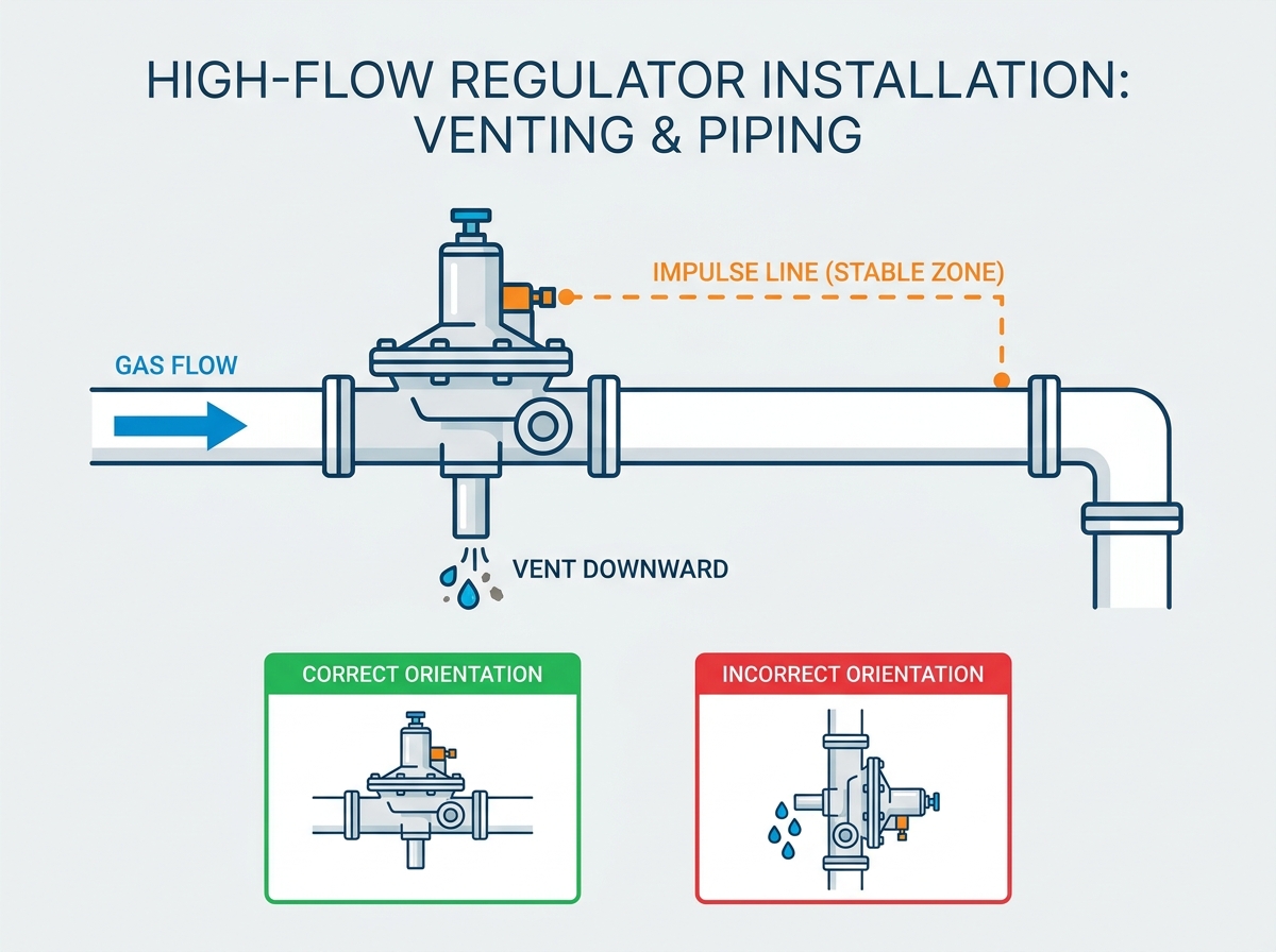
The breather hole performs a vital mechanical function. It allows ambient air to enter the upper casing. It pushes this air out when internal mechanisms shift. This breathing lets the main mechanism move freely. A blocked port paralyzes the internal spring instantly. Furthermore, it serves as the ultimate safety escape. A ruptured rubber seal forces raw fuel upward. Proper regulator venting directs this fuel away safely.
Directionality dictates site safety. You must angle external exhaust ports downward. Downward placement repels rain, snow, and ice buildup. It also stops insects from building nests inside the port. Mud daubers frequently clog unprotected openings. Indoor applications demand specialized handling. You cannot release fuel into enclosed rooms. You must pipe indoor exhausts to a safe exterior atmosphere. Code compliance depends heavily on this step.
Pipe diameter directly impacts safety responses. You must never restrict escaping fuel. Friction slows down the exhaust rate over long distances. You must step up the pipe diameter for extended runs. Excessive backpressure paralyzes the internal safety mechanisms. It delays critical lock-up responses during emergency surges. Engineers must calculate equivalent pipe lengths meticulously.
Vent Line Sizing Escalation Chart
| Original Port Size | Run Length: 0 - 10 ft | Run Length: 10 - 40 ft | Run Length: 40+ ft |
|---|---|---|---|
| 1/4 inch | Use 1/4 inch pipe | Increase to 3/8 inch pipe | Increase to 1/2 inch pipe |
| 1/2 inch | Use 1/2 inch pipe | Increase to 3/4 inch pipe | Increase to 1 inch pipe |
| 3/4 inch | Use 3/4 inch pipe | Increase to 1 inch pipe | Increase to 1-1/4 inch pipe |
Upstream restrictions destroy downstream performance. Assess the supply pipe diameter carefully. High-capacity units cannot miraculously compensate for starved supply lines. Undersized feed pipes cause massive pressure drops during high demand. Your inlet velocity exceeds acceptable limits quickly. This generates severe acoustic noise and vibration.
You must protect internal precision seats from physical damage. Install heavy-duty Y-strainers upstream. Weld slag and pipe scale act like sandpaper. These particulates destroy soft rubber seals instantly. Damaged seals leak dangerously when the system demands a total shutoff. A simple filter prevents catastrophic internal failure.
Downstream layouts demand smooth, laminar flow. Avoid installing isolation valves right after the outlet flange. Tight elbows create chaotic turbulence. Sharp diameter reductions bottleneck the expanding gas. Give the fluid room to stabilize. Provide a long straight run to establish a predictable flow profile. Executing perfect gas regulator piping prevents the internal mechanisms from oscillating wildly.
Continuous industrial processes require redundant safety layers. You should build a parallel dual-regulator manifold. Engineers call this a worker/monitor arrangement. The monitor stays wide open during normal operation. It steps in instantly if the primary worker fails. Alternatively, construct a manual bypass loop. This allows technicians to perform maintenance without shutting down the facility.
Steps for Proper Bypass and Manifold Setup:
Large pilot-operated units rely on external feedback. They do not sense pressure internally. They use an external sensing tube. The impulse line monitors downstream conditions directly. It commands the main valve to open or close based on demand. This feedback loop is the brain of high-capacity systems.
Proximity determines sensing accuracy completely. You must tap this tube into a perfectly straight pipe section. Industry guidelines recommend a distance of five to ten pipe diameters downstream. Do not tap near elbows or diameter transitions. High-velocity zones create a venturi effect. This effect artificially lowers the localized pressure. The sensing tube reads this false low. It commands the main valve to open unnecessarily. The entire system then hunts and oscillates violently.
Implementation demands strict physical routing. Pitch the sensing tube backward toward the main pipeline. Gravity pulls liquid condensate away from the sensitive control pilot. Fluid must never enter the pilot chamber. A flooded control chamber renders the entire unit useless.
Impulse Line Best Practices:
Commissioning transforms a physical build into an active energy system. Never skip the pre-activation checklist. Verify cast flow arrows against your approved engineering schematics. Confirm all exhaust ports point downward. Inspect the sensing tubing for secure, leak-free compression fittings. Visual confirmation prevents initial launch failures.
Pressurize the system with extreme caution. Crack the upstream isolation valve open slowly. Instantaneous pressure causes violent pneumatic shock. A massive shockwave can tear the internal rubber seals apart. Allow the intermediate pressure to equalize gradually before opening downstream supply valves.
Execute a zero-flow lock-up test immediately. Close all downstream burner valves. Trap the pressure in the intermediate pipe section. Monitor the gauge closely. The internal seat must seal perfectly. The gauge needle should freeze in place. If pressure creeps upward, debris has compromised the main seal. You must disassemble and clean the unit.
Document your final operating setpoints clearly. Establish a rigid preventative maintenance schedule. Plan routine visual inspections for exhaust screens. Clean the upstream strainers annually. Ensure a certified technician signs off on the final deployment to maintain compliance and warranty validity.
A: Yes, conditionally. It depends on the manufacturer's specifications. However, vertical installation may require setpoint recalibration due to gravity and necessitates careful vent positioning to prevent moisture buildup.
A: A blocked vent traps air in the spring casing, restricting diaphragm movement. This leads to sluggish response, failure to open under load, or dangerous over-pressurization downstream. It also traps explosive fuel indoors during a seal rupture.
A: Industry standards generally recommend tapping the impulse line 5 to 10 pipe diameters downstream of the regulator, in a straight section of pipe free from turbulence-inducing fittings. Tapping too close causes violent mechanical oscillation.