lucy@zlwyindustry.com
+86-158-1688-2025
Please Choose Your Language
- All
- Product Name
- Product Keyword
- Product Model
- Product Summary
- Product Description
- Multi Field Search

Views: 0 Author: Site Editor Publish Time: 2026-07-26 Origin: Site


Facilities actively install dual fuel burners to leverage fuel arbitrage, survive natural gas curtailments, and ensure continuous steam production. Plant managers rely heavily on this operational flexibility to keep critical heat processes running during volatile supply periods. However, switching fuels is never as simple as just flipping a switch. A poorly executed transition frequently leads to frustrating boiler lockouts, dangerous unburned fuel hazards, or incredibly costly downtime. Without precise mechanical control, you expose your facility to severe explosive risks.
This article aims to deconstruct the mechanics, Burner Management System (BMS) logic, and safety compliance required for a reliable dual fuel burner changeover sequence. You will learn how to evaluate system upgrades, meet insurance mandates, and protect your plant from unexpected interruptions. By mastering these fundamental procedures, operators can effectively maintain high efficiency and uncompromising safety across all combustion equipment.
Modern industrial facilities operate in an era of unpredictable energy markets. A reliable gas oil burner changeover provides a crucial buffer against these fluctuations. Plant leaders must continuously balance operational continuity against inherent safety risks. When gas pressure drops unexpectedly, operators feel immense pressure to switch fuels quickly. However, firing a new fuel introduces mandatory safety requirements. Rushing this process bypasses critical safety checks, often resulting in catastrophic equipment failure.
You cannot sacrifice safety for speed. Every fuel transition demands precise timing and verifiable valve closures. If operators force a rapid switch to prevent a boiler temperature drop, they risk introducing raw fuel into a hot, oxygen-rich environment. This scenario causes explosive light-offs. Therefore, a proper system relies on automated logic to govern the transition. It removes human error and enforces mandatory purge times.
Beyond emergency backup, dual fuel capabilities offer significant cost advantages. Natural gas spot prices sometimes spike during extreme weather events. When these spikes occur, facilities can dynamically switch to backup light or heavy fuel oil. This flexibility protects profit margins. Operators can monitor market rates and seamlessly transition to the cheaper energy source. They maintain production targets while optimizing daily operational expenses.
How do we measure a successful fuel switch? First, the system must yield zero safety trips during the transition. False trips stall production and force operators into lengthy manual reset procedures. Second, the sequence should minimize the boiler temperature drop. Heat loss impacts downstream production quality. Finally, the entire mechanism must demonstrate verifiable compliance with facility insurance standards. Insurers demand strict adherence to redundant safety protocols before underwriting industrial risks.
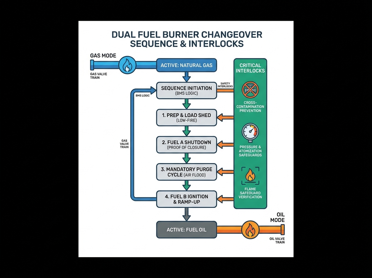
Transitioning between fuels involves a highly choreographed series of mechanical and electrical events. The Burner Management System (BMS) orchestrates these steps to guarantee maximum safety. Let us break down the exact sequence operators follow during a standard transition.
Operators must prepare the boiler before initiating any fuel change. You cannot switch fuels while operating at high fire. The BMS first drives the burner to a low-fire position. This step stabilizes the internal combustion dynamics. It reduces the fuel flow rate and minimizes the initial thermal shock. Once the burner reaches the proven low-fire position, the system permits the transition to begin.
The system must safely terminate the active fuel source. The BMS de-energizes the primary fuel safety shutoff valves (SSOV). Power loss forces these solenoid or pneumatic valves to snap shut immediately. However, simply removing power is not enough. The BMS must verify valve closure via Proof of Closure (POC) switches. These microswitches confirm mechanical isolation. If a valve remains partially open, the sequence halts instantly.
Safety codes require a thorough purge cycle before introducing the second fuel. The combustion blower floods the chamber with fresh air. This action evacuates any residual combustible gases from the previous fuel. Operators must balance this requirement carefully. Meeting standard air-change requirements is non-negotiable. Yet, pushing too much cold air into a hot boiler causes excessive thermal shock to the boiler tubes. Engineers calculate the exact purge volume to satisfy safety codes while protecting the metallurgical integrity of the vessel.
Following the purge, the system prepares to light the secondary fuel. The BMS establishes the pilot flame first. Once the flame scanner verifies a strong pilot, the system activates the secondary main fuel train. Fuel enters the chamber and ignites. UV/IR scanners continually monitor the main flame. After verifying stable combustion, the BMS releases control back to the firing rate controller. The boiler then ramps back up to its standard operational firing rate.
The BMS relies on a network of sensors to manage the transition safely. These burner interlocks act as the primary defense against catastrophic failures. They continuously monitor physical parameters and interrupt the sequence if any value falls outside safe limits.
You must prevent two different fuels from entering the burner simultaneously. Mechanical and electrical interlocks ensure gas valves and oil valves cannot open at the same time. The BMS logic acts as a strict gatekeeper.
Combustion relies on precise fluid pressure. High and low gas pressure switches monitor the natural gas train. If pressure spikes, the flame could blow off the burner head. If pressure drops, the flame could travel backward. Oil systems require similar oil pressure interlocks.
Furthermore, heavy and light oils require atomization to burn cleanly. The system uses steam or compressed air to break the oil into a fine mist. Interlocks verify atomizing medium pressure before allowing oil valves to open. If atomizing pressure drops, the oil will stream instead of spray, causing severe pooling and unburned fuel hazards.
Different fuels produce different flame characteristics. Natural gas burns with a distinctly different spectral footprint compared to fuel oil. The flame safeguard system must recognize these differences. Modern UV/IR scanners require specific threshold adjustments during the handoff. The BMS automatically switches its scanning parameters to match the incoming fuel profile. This ensures the system does not falsely trip due to an unrecognized flame signature.
Transitioning between physical states—from a gas to a liquid—introduces complex fluid dynamic challenges. Managing these fluids correctly prevents equipment damage and environmental hazards.
Transitioning away from oil requires an active scavenging step. Operators cannot simply shut off the oil valves and leave the burner. Residual oil trapped in the burner gun will bake from the radiant heat of the furnace. This process causes severe carbon buildup, known as coking, inside the nozzle. The BMS initiates an automated purge step. It blows high-pressure steam or compressed air through the oil passages. This action clears the gun entirely, ensuring it remains clean and ready for the next emergency transition.
Gas trains utilize a specific valve configuration known as double block and bleed. This setup features two main shutoff valves in series. A vent valve sits between them. During the changeover to oil, both main gas valves close. Simultaneously, the vent valve opens to the atmosphere. If the first gas valve leaks, the gas safely vents outside the building rather than seeping into the combustion chamber. This mechanism ensures absolute zero gas leakage while firing on oil.
Industrial environments punish mechanical equipment. High-frequency transitions accelerate wear and tear on solenoid valves and linkages. Cheap valve trains often fail under these demanding conditions. Seat materials degrade, springs lose tension, and linkages bind. Plant managers must invest in industrial-grade components. Upgrading to robust, heavy-duty valves prevents premature failure and ensures the safety systems function correctly during critical moments.
Facilities choose different levels of automation based on budget, operator availability, and risk tolerance. Understanding these options helps you select the right fuel switching sequence for your specific plant architecture.
Changeover Automation Comparison Chart
| System Type | Operator Intervention | Capital Expenditure | Transition Speed | Best Fit Scenario |
|---|---|---|---|---|
| Manual | High (Swaps guns, connects hoses) | Low | Slow (30+ minutes) | Rare transitions, high staff availability |
| Semi-Automatic | Medium (Initiates switch via HMI) | Medium | Moderate (5-10 minutes) | Frequent economic fuel arbitrage |
| Fully Automatic | Zero (BMS detects pressure drops) | High | Fast (3-5 minutes) | Critical processes, unmanned boiler rooms |
A manual system requires an operator to physically swap burner guns. They must manually connect fuel hoses and manipulate physical limit switches. While this offers low capital expenditure, it drastically increases transition time. A semi-automatic system bridges the gap. An operator initiates the switch from the HMI screen. The BMS then takes over, handling the purge and sequence automatically. Finally, fully automatic systems offer zero-intervention redundancy. They transition automatically based on utility header pressure drops. They demand higher initial investment and stringent maintenance but provide ultimate peace of mind.
You must specify systems that natively comply with major safety standards. Look for FM Global, UL, and NFPA 85 certifications. Off-the-shelf compliant systems are far safer than custom solutions. Avoid facilities relying on custom, hard-to-maintain PLC workarounds. Proprietary code often breaks during controller updates. Standardized BMS platforms ensure long-term scalability and easy troubleshooting for incoming technicians.
Before requesting vendor bids, assess your facility internally. Determine your actual tolerance for unexpected downtime. Evaluate your typical operator availability across all shifts. Review your specific insurance mandates regarding fuel train redundancies. Armed with this data, you can approach combustion vendors confidently. You will know exactly which level of automation fits your operational reality and budget constraints.
A reliable dual fuel transition is fundamentally a matter of integrating robust mechanical hardware with uncompromising BMS logic. Facilities cannot rely on outdated, manual workarounds when handling highly combustible materials. Plant leaders must prioritize verifiable safety interlocks over minor speed improvements during the purge process.
Focus your maintenance budgets on industrial-grade double block and bleed valves. Ensure your flame scanners correctly differentiate between distinct fuel profiles. Most importantly, demand strong post-installation support from your selected combustion vendors. To safeguard your facility against the next unexpected utility disruption, we strongly recommend scheduling a comprehensive site audit. Have a certified combustion engineer review your current BMS logic and physical fuel train hardware immediately.
A: The transition timeframe typically ranges from 3 to 15 minutes. It depends heavily on the mandatory purge cycle duration, total boiler volume, and your chosen automation level. Fully automatic systems switch much faster than manual setups, but safety codes strictly dictate minimum air-change times before re-ignition.
A: Upgrading usually requires a complete BMS controller replacement. A dual fuel system demands significantly expanded I/O capabilities. The controller needs extra inputs for additional interlocks, pressure switches, and complex dual-scanner setups. Legacy single-fuel panels rarely possess the required expansion slots or approved programming logic.
A: Trips frequently occur due to uncalibrated flame scanners failing to recognize the darker oil flame profile. Other common culprits include sluggish oil pump pressure buildup or atomizing air pressure faults. If atomizing steam pressure dips slightly below the interlock threshold, the BMS immediately aborts the sequence for safety.