lucy@zlwyindustry.com
+86-158-1688-2025
Please Choose Your Language
- All
- Product Name
- Product Keyword
- Product Model
- Product Summary
- Product Description
- Multi Field Search

Views: 0 Author: Site Editor Publish Time: 2026-08-09 Origin: Site


Mismatching a burner oil pump to system requirements doesn’t just reduce combustion efficiency. It leads to premature pump failure, cavitation, and costly unplanned downtime. Field technicians frequently discover standardized factory settings rarely align perfectly with specific site conditions. Specifying the right pump requires balancing the physical properties of the fuel. You must weigh these variables against the rigorous mechanical demands of the burner nozzle and the surrounding piping network. This guide provides a technical evaluation framework for navigating the critical variables of fluid dynamics and mechanical sizing. We outline actionable methods ensuring optimal atomization and long-term system longevity. Mastering these complex interactions separates a smoothly running boiler from a persistent operational headache.
Successful installations require treating system dynamics as a continuously linked performance curve. You cannot isolate a single metric without affecting the others. Fluid dynamics dictate how liquids behave under mechanical stress inside a closed loop. Changing one variable forces an immediate reaction across the entire pumping mechanism.
Consider how these three primary metrics interact during daily operation:
You must also carefully evaluate the wear factor. Higher viscosity fuels naturally lubricate the internal gearset. This lubrication protects metal surfaces but increases flow resistance and pressure drops across the piping system. Conversely, modern ultra-low sulfur diesel (ULSD) or kerosene presents a different challenge. These lighter fuels possess significantly lower lubricity. Thin fluids easily bypass internal seals, increasing the risk of mechanical wear and internal leakage over time.
Properly navigating burner oil pump selection viscosity flow pressure variables establishes a reliable foundation. You must abandon the assumption of isolated specifications. Instead, map out a holistic performance curve reflecting real-world fluid behavior.
Different applications rely on vastly different hydrocarbon blends. Understanding the baseline kinematic viscosity of your specific fuel represents the first step in equipment evaluation. We measure this property primarily in Centistokes (cSt) or Saybolt Universal Seconds (SSU).
| Fuel Grade | Typical Viscosity Range (cSt at 40°C) | Common Application | Pre-Heating Requirement |
|---|---|---|---|
| No. 2 Heating Oil | 2.0 - 3.4 | Residential & Light Commercial | Rarely needed |
| No. 4 Fuel Oil | 5.5 - 24.0 | Medium Commercial Boilers | Sometimes required |
| No. 6 Fuel Oil (Bunker C) | 90.0 - 600.0+ | Heavy Industrial & Marine | Mandatory |
| Biodiesel Blends (B20) | 3.5 - 5.0 | Eco-friendly Retrofits | Varies by climate |
Environmental and operational temperatures drastically alter these baseline measurements. A fuel performing perfectly at room temperature will behave like a solid sludge during a freezing winter night. Colder temperatures thicken the fluid, increasing suction line resistance exponentially. Engineers rely heavily on fuel heaters for heavier grades like No. 6 oil. Heaters reduce the fluid's thickness, bringing the resistance down to fit within the operational limits of the selected gearset.
Performance suffers severely when temperatures stray from the calculated baseline. When fuel viscosity runs too high, the gearset struggles to pull the liquid from the tank. This extreme resistance causes severe cavitation, starving the nozzle and potentially overloading the electric motor. Conversely, if the fluid becomes too thin from excessive heating, the gearset fails to generate sufficient pressure. Thin fluids slip through the mechanical clearances, resulting in poor nozzle atomization and unstable combustion.
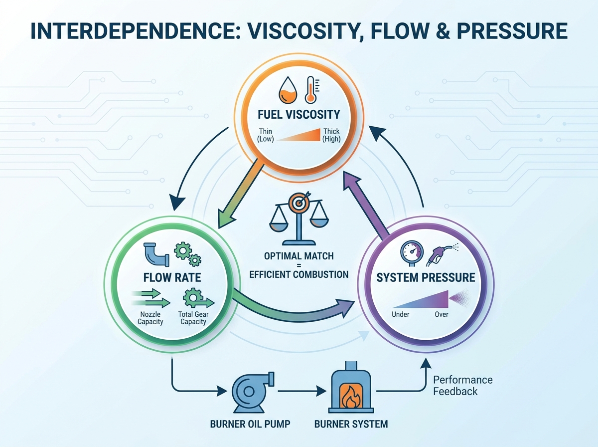
Many technicians confuse the burner's firing rate with the total required fluid delivery. The firing rate only dictates what the nozzle actively consumes during combustion. The actual required oil pump flow rate represents the total fluid volume the internal gearset must move to maintain system stability. You must size the equipment based on gear capacity rather than just the nozzle capacity.
Piping configurations dictate how we calculate this capacity:
When installing a two-pipe setup, technicians must install a specific bypass plug inside the casing. This plug redirects the unburned fluid into the return line. Forgetting this plug pressurizes the internal shaft seal, causing immediate and catastrophic leaks.
Accurate oil pump sizing relies on established engineering margins. A standard rule of thumb involves over-sizing the gear capacity by 20% to 30% above the maximum nozzle consumption. This margin compensates for eventual mechanical wear and the unavoidable internal slip occurring over years of active service. Over-sizing ensures you maintain adequate delivery even as the internal components slowly degrade.
Mechanical pressure exists solely to force liquid through the restrictive orifice of the nozzle. This force accelerates the fluid to a velocity high enough to shatter it into a combustible droplet mist. Without adequate velocity, the fuel exits as a solid stream, rendering ignition impossible.
Standard and high-efficiency applications require different mechanical approaches. Traditional systems historically standardized around 100 PSI. This legacy setting worked well for older, less restrictive nozzles burning standard No. 2 oil. However, modern high-efficiency burners demand much finer atomization to meet strict environmental emission standards. These contemporary systems routinely require operating levels between 140 and 200 PSI. The increased force creates smaller, more uniform droplets, promoting a hotter and cleaner flame.
Deviating from the manufacturer's specified pressure range triggers immediate combustion issues. You must understand the consequences of improper calibration:
Consistently matching the burner pump pressure to the specific nozzle design ensures optimal fuel-to-air mixing. This precise calibration prevents dangerous soot accumulation and maximizes overall thermal output.
Never fall into the factory settings trap. Manufacturers ship their products calibrated to universally accepted baselines, commonly resting at 100 or 150 PSI. Assuming these out-of-the-box settings are correct for your specific installation is a dangerous oversight. Every field environment features unique piping lengths, varying suction lifts, and distinct fluid temperatures.
Mandatory field testing during startup prevents early component failure. You must utilize calibrated pressure and vacuum gauges before turning the equipment over to the facility owner. Attach a pressure gauge to the dedicated bleeder port to verify delivery force matches the nozzle specifications. Simultaneously, attach a vacuum gauge to the suction port to measure intake resistance.
Monitoring these gauges provides immediate diagnostic feedback for troubleshooting common failures. High vacuum readings typically indicate severe suction line restrictions. Clogged filters, kinked copper tubing, or excessively thick fluid can trigger these high readings. If the vacuum exceeds 10 to 12 inches of mercury in a two-pipe configuration, you risk immediate cavitation.
Fluctuating pressure readings highlight entirely different problems. A bouncing gauge needle almost always indicates air leaking into the suction line. Loose flare fittings or compromised filter gaskets allow air to mix with the liquid, breaking the hydraulic seal. Bouncing needles can also indicate severe cavitation where the fluid literally boils apart under extreme negative pressure. Verifying all connections and ensuring adequate line sizing will stabilize the delivery force and protect the internal gearset.
Successful deployment relies heavily on evaluating the system’s holistic hydraulic requirements. You cannot achieve reliable combustion by merely guessing at flow rates or accepting unverified factory configurations. Fluid thickness, gearset capacity, and delivery force remain permanently linked throughout the equipment's operational lifespan.
Follow these actionable next steps before finalizing your next installation:
Taking a calculated, engineering-first approach eliminates unpredictable performance. Measuring your variables accurately ensures cleaner atomization, prevents catastrophic mechanical leaks, and guarantees long-term operational stability.
A: Colder temperatures increase viscosity, which increases suction line resistance. This may require a pump with a higher vacuum rating or a larger motor to prevent cavitation. You must select equipment capable of handling the highest expected resistance during the coldest operating months.
A: While increasing pressure increases the flow rate through the nozzle marginally, it is not a primary method for oil pump sizing. Pressure should be set strictly to achieve proper atomization according to the nozzle manufacturer's specifications. Always use gearset capacity to determine proper flow delivery.
A: Standard pumps designed for No. 2 oil will experience severe cavitation, seal failure, and motor burnout if forced to pump high-viscosity fuels without proper pre-heating and specialized internal clearances. The heavy fluid creates excessive drag that standard motors simply cannot overcome.
A: Erratic pressure is rarely a factory defect. It typically indicates an air leak in the suction line, a missing bypass plug in a two-pipe system, or a mismatch between the fuel viscosity and the pump's rotational speed. Check all flare fittings and filter gaskets immediately.