lucy@zlwyindustry.com
+86-158-1688-2025
Please Choose Your Language
- All
- Product Name
- Product Keyword
- Product Model
- Product Summary
- Product Description
- Multi Field Search

Views: 0 Author: Site Editor Publish Time: 2026-07-30 Origin: Site


Precise combustion control relies heavily on mechanical execution. Adjusting the air-fuel ratio requires absolute accuracy. Specifying the wrong motor leads to bad operational outcomes. You might see inefficient fuel consumption almost immediately. Harmful emissions could increase rapidly. Safety lockouts may also shut down your entire process. Standard industrial motors often fail in severe combustion environments. Burner applications demand highly specialized hardware. You must evaluate dynamic loads and control precision thoroughly. You also need rapid-response safety compliance for emergency situations. Our goal is to help you navigate this process successfully. We provide an evidence-based framework for evaluating components. You will learn how to shortlist options effectively. We will explore physical force, sweeping motion, speed, and environmental resilience.
Why does specialized hardware matter? Mechanical specifications link directly to your operational outcomes. Boiler efficiency drops significantly when oxygen levels fluctuate. A poorly positioned damper wastes expensive fuel. It also produces harmful emissions like nitrogen oxides and carbon monoxide. These pollutants trigger environmental compliance penalties quickly.
We must look closely at the physical realities of failure. Component sizing presents a major challenge. Undersized parts stall under heavy loads. They overheat rapidly during continuous operation. Conversely, oversized components create different problems. They add unnecessary physical bulk. Massive motors respond sluggishly to micro-adjustments. You lose the crisp control required for modern boilers.
Effective burner actuator selection solves these mechanical problems. It relies on a rigorous evaluation framework. You must analyze three critical dimensions simultaneously. First, you evaluate the mechanical load requirement. Second, you determine the necessary positional accuracy. Finally, you assess the dynamic response speed. Balancing this triad guarantees stable operation.
Consider these common failures caused by improper selection:
You cannot guess load requirements safely. Proper burner servo motor torque sizing forms the foundation of system stability. You must define your operating baseline correctly. Differentiate clearly between continuous running load and peak breakaway friction. A damper requires minimal force to stay in motion. However, starting that motion demands significant power.
Closed dampers stick aggressively over time. Carbon deposits build up around the edges. Heat warps the metal frames slightly. Overcoming this static stiction requires maximum servo motor torque. If your motor cannot break this initial friction, the burner locks out entirely.
You need accurate calculations for safe operation. Break down the opposing forces systematically.
We highly recommend following established engineering best practices here. Apply a verifiable safety margin to your calculations. Add a 20-30% buffer to your measured peak torque. This margin accounts for inevitable soot buildup. It also covers mechanical degradation over years of service. However, avoid arbitrary oversizing beyond this margin.
The following chart illustrates different load phases you must calculate during system design.
| Load Phase | Description | Importance for Sizing |
|---|---|---|
| Breakaway Phase | Force needed to move from a dead stop. | Highest peak requirement. Defines the absolute motor capacity. |
| Acceleration Phase | Force required to reach operating speed quickly. | Impacts dynamic response and cross-limiting tracking. |
| Continuous Phase | Constant force during steady-state modulation. | Prevents thermal overload during long firing cycles. |
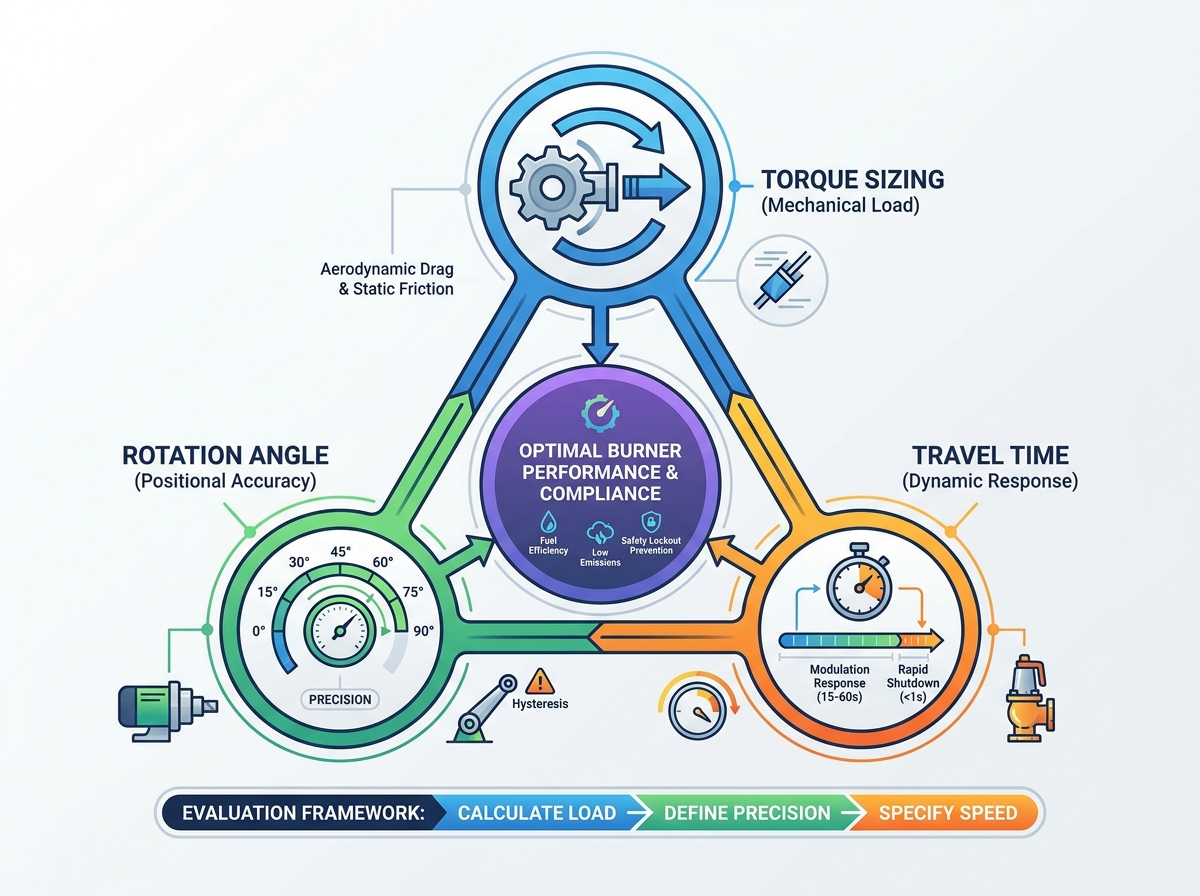
Positional accuracy directly impacts your combustion quality. The total rotation angle defines your turndown ratio. Turndown ratio is the maximum firing rate divided by the minimum. To achieve a 10:1 ratio, you need extreme precision at the low end. A wider sweeping arc often provides finer flow resolution.
High-resolution movement prevents "hunting" behavior. Hunting occurs when a control loop constantly overshoots its target. The motor moves back and forth endlessly. This wears out internal gears quickly. Precise angular control eliminates this damaging hysteresis.
You must evaluate linkage systems versus direct drive configurations carefully. Traditional mechanical linkages translate rotary motion into linear motion. This creates non-linear geometry. A ten-degree turn at the start produces different airflow than a ten-degree turn at the end. Linkage joints also introduce deadband. Deadband is the sloppy movement before the damper actually turns.
Direct-coupled solutions eliminate non-linear movement entirely. The motor shaft mounts straight onto the damper shaft. You get a perfect 1:1 ratio. Every fraction of a degree translates directly into damper movement. This direct approach simplifies calibration immensely.
Step resolution matters greatly for strict emission controls. Define your required internal positioning steps carefully. Many modern low-NOx systems require 0.1° accuracy. You need this micro-stepping capability to maintain strict oxygen trim control loops. The exhaust sensor reads the oxygen level. It sends a signal back to the controller. The controller commands a tiny adjustment. Without high step resolution, the system cannot execute this fine tune.
Burners track rapid changes in facility demand. Modulation response depends heavily on physical actuator speed. Evaluate how your actuator travel time impacts this tracking ability. Moving 90 degrees in 15 seconds behaves quite differently than 30 seconds. Sluggish actuators cause sudden boiler pressure drops.
Cross-limiting control logic makes speed crucial. Air must always lead fuel when increasing power. Fuel must lead air when decreasing power. This prevents dangerous fuel-rich mixtures. If travel times do not match perfectly, this logic fails. You risk generating heavy soot or blowing out the flame entirely.
Strict compliance guidelines add hard safety constraints. Align your requirements with industry safety codes immediately. Standards like NFPA 85 or EN 676 dictate specific emergency actions. You need rapid-closing mechanisms for absolute safety. Emergency fuel shut-off conditions require closure in under one to two seconds. Your hardware must support independent running and closing speeds.
Speed also affects mandatory purging efficiency. Pre-purge and post-purge cycles consume significant energy. The fan blows cold air through the hot furnace. This removes unburned gases safely. Optimized actuator speeds reduce these cycle durations safely. You open the damper fully, purge quickly, and close it rapidly for light-off. You save electrical power on the fan motor. You also conserve valuable thermal energy by minimizing cold drafts.
Burner decks create incredibly hostile operating environments. You must evaluate environmental ratings thoroughly before purchasing. Standard motors fail rapidly near industrial furnaces. Check the ambient temperature tolerance first. Radiant heat damages internal electronics quickly. It also degrades gear lubrication.
Vibration resistance matters for fan-mounted applications. Fans generate constant harmonic shaking. Look for ruggedized housings. Verify IP or NEMA enclosures to stop intrusive dust and moisture. An IP65 rating provides good dust protection. However, an IP67 rating withstands temporary water immersion during washdowns.
Many facilities contain hazardous locations. Petrochemical plants harbor explosive atmospheres. Specific grain or dust processes share these identical risks. You must verify ATEX, IECEx, or UL certifications. These ratings guarantee the casing contains any internal sparks. They prevent catastrophic facility ignition events.
Control system integration requires careful forward planning. Assess compatibility with your existing Burner Management Systems (BMS). Older setups use simple analog wiring. Many plants still rely on standard 4-20mA loops. These loops only provide basic position confirmation. Modern systems utilize advanced digital communications. Protocols like Modbus RTU, CANopen, or PROFINET offer superior control.
This comparison chart breaks down common communication protocols used in combustion environments.
| Protocol Type | Wiring Complexity | Diagnostic Feedback Level |
|---|---|---|
| Analog 4-20mA | High (Requires dedicated signal wire pairs) | Very Low (Only confirms current position) |
| Modbus RTU | Medium (Allows daisy-chain layouts) | Moderate (Provides basic fault codes) |
| PROFINET | Low (Uses standard industrial Ethernet) | High (Delivers real-time predictive data) |
You need a structured method to shortlist components accurately. Start by verifying manufacturer data sheets intensely. Learn how to read provided torque-speed curves. Make sure the motor maintains necessary force at your desired speed. Magnetic force often drops significantly at higher speeds. You cannot assume maximum force applies across the entire speed range.
Look beyond the initial physical dimensions. Evaluate the entire operational lifecycle rating. Check the expected maintenance cycles thoroughly. Investigate the specific lubrication needs for internal gear trains. Some units require messy manual greasing annually. Others offer sealed, maintenance-free designs. Review the warranty terms provided by the manufacturer. These technical parameters determine long-term reliability heavily.
Move directly to the validation phase next. Request an engineering sample if your project allows it. Review 3D CAD models to check precise footprint constraints. Burner decks often feature extremely limited space for new hardware. Piping and electrical conduits block larger housings. Finally, consult directly with vendor application engineers. They provide final validation for your unique facility setup. They catch subtle errors you might overlook.
Proper evaluation secures safe, efficient facility operations. Sizing components accurately prevents unexpected catastrophic failures. You must balance physical force, positioning accuracy, and operational speed. These core elements remain non-negotiable for optimized combustion. Careful calculation always trumps hopeful guesswork.
Relying on empirical load data prevents premature mechanical wear. A structured approach guarantees your equipment handles dynamic aerodynamic forces easily. It also ensures you meet strict regulatory emissions targets. Your operators gain a stable, responsive, and safer boiler environment.
Take proactive action today to secure your system. Download a technical sizing worksheet from a trusted vendor. You can also access an online product configurator for initial calculations. Contact a specialized sales engineering team for a site-specific evaluation. They will help you finalize your exact mechanical specifications.
A: High ambient heat causes severe thermal derating. As internal coil temperatures rise, magnetic efficiency drops noticeably. Manufacturers provide specific derating curves for these conditions. If your burner deck exceeds 60°C, you lose significant output force. Always select hardware featuring built-in heat dissipation fins or higher insulation classes.
A: Standard industrial motors lack specific fail-safe mechanisms entirely. They rarely carry required combustion safety certifications. Burner environments demand rapid-closure springs or redundant mechanical feedback loops. If facility power fails, you must guarantee immediate damper closure. Standard drives do not offer this critical emergency function reliably.
A: Modulation typically requires 10 to 60 seconds for a full 90-degree sweep. This speed allows stable, precise tracking of boiler loads. However, emergency situations demand different capabilities. Rapid shutdown requirements dictate absolute closure in under one to two seconds. You often need distinct running and closing speeds.
A: You can measure this practically before specifying new hardware. Disconnect the existing mechanical linkage entirely. Attach a calibrated torque wrench directly to the main damper shaft. Pull the wrench slowly from a fully closed position. Record the maximum reading just as the damper breaks free. Always add a safety margin.