lucy@zlwyindustry.com
+86-158-1688-2025
Please Choose Your Language
- All
- Product Name
- Product Keyword
- Product Model
- Product Summary
- Product Description
- Multi Field Search

Views: 0 Author: Site Editor Publish Time: 2026-08-21 Origin: Site


Operating a pressure-driven system with poorly calibrated components carries massive operational risks. You might face premature equipment wear, staggering energy waste, and dangerously unstable line pressure on a daily basis. At the heart of this stability lies the fundamental relationship between the activation threshold and the operational gap before shutdown. Misalignment between these two values frequently triggers rapid short-cycling. This destructive phenomenon quickly burns out contactors and destroys expensive pump motors.
We wrote this guide to provide a verifiable, step-by-step framework. You will learn how to safely adjust, test, and maintain these mechanical controls. By following these strict protocols, you can easily optimize system longevity. You will ensure reliable, repeatable performance across various commercial and industrial applications without guessing.
To master pressure regulation, we must first define the core metrics driving system behavior. The pressure switch setpoint, commonly known as the cut-in, represents the exact pressure threshold. It engages your pump, compressor, or heating unit. Conversely, the cut-out represents the upper limit. This ceiling tells your mechanical system to stop operating. The mathematical difference between these two points is the switch differential. It forms the foundation of stable fluid and air management.
Engineers design a specific buffer zone between the on and off states. We refer to this engineered deadband as hysteresis. It prevents a system from rapidly toggling on and off around a single pressure point. Without this intentional delay, any minor pressure drop would trigger an immediate restart.
Bypassing or overly compressing this deadband carries severe operational risks. If you set the gap too narrow, your equipment will short-cycle violently. This rapid switching causes extreme contactor wear inside the electrical housing. It generates massive heat build-up. Eventually, this heat leads directly to motor burnout and catastrophic relay failures.
Different environments demand vastly different parameter tolerances. We can contrast standard water systems against critical industrial applications to understand these demands.
| System Type | Typical Cut-In | Typical Cut-Out | Differential Purpose |
|---|---|---|---|
| Residential Water Pump | 30 PSI | 50 PSI | Maximize motor cooling time between runs. |
| Commercial Air Compressor | 90 PSI | 120 PSI | Maintain steady tool power without continuous running. |
| Industrial Burner Control | Varies closely | Varies closely | Ensure precise fuel-to-air ratios for safe combustion. |
You must prepare your equipment safely before turning a single wrench. Pressure systems store massive amounts of kinetic and electrical energy. Handling them carelessly leads to severe injury or equipment destruction.
Lockout/Tagout (LOTO) procedures are strictly mandatory. You must disconnect all power at the main breaker. Never adjust exposed mechanical contacts on a live circuit. The springs and metal brackets sit dangerously close to high-voltage terminals. An accidental slip of your screwdriver can easily arc the electrical current.
You must isolate the system completely from the main line. Shut the primary isolation valves. Open the drain valves to release all residual line pressure safely. You must achieve a true zero-pressure state before removing the switch housing. Adjusting tension springs while they remain under active hydraulic or pneumatic load yields entirely false readings. It ruins your calibration efforts instantly.
Calibration fails if the surrounding components operate poorly. You must verify the baseline environment first.
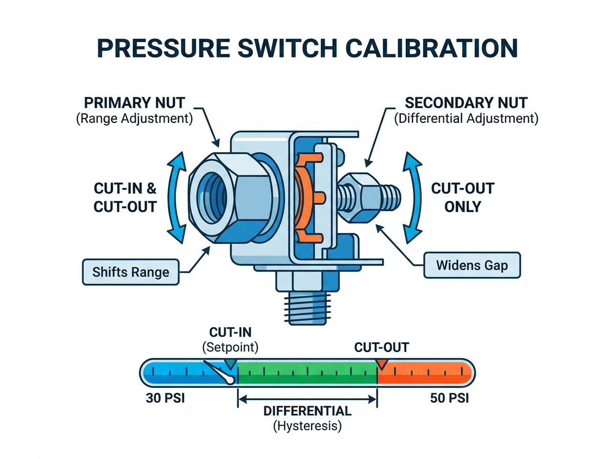
Standard commercial and industrial switches utilize a highly predictable mechanical design. We will use a standard Square D-style dual-nut model as our primary example. Identifying the internal anatomy ensures you manipulate the correct variables.
Remove the plastic or metal housing carefully. Look at the exposed mechanism. You will identify two vertical threaded shafts equipped with tension springs and adjustment nuts.
You must establish your base activation threshold first. Place your wrench on the large nut.
Clockwise rotation increases both the cut-in and cut-out values simultaneously. The entire operating bracket shifts upward. Counter-clockwise rotation decreases both values equally. They shift downward together. The actual gap between them remains identical during this step.
As a strict rule of thumb, turn the nut in standard, measured increments. Use half-turns. Stop and measure the PSI change per rotation to establish a predictable adjustment ratio for your specific model.
Now you will manipulate the operational gap. Place your wrench on the small nut.
Clockwise rotation increases the cut-out pressure without changing your established cut-in point. This action effectively widens the pressure switch setpoint differential. Conversely, counter-clockwise rotation lowers the cut-out limit. This narrows the gap between activation and deactivation.
Close your drain valves. Restore electrical power to the circuit. You must now monitor a full mechanical cycle under live conditions.
Watch the system gauge closely. Document the exact cut-in and cut-out points as they happen mechanically. Open a downstream valve to bleed pressure slowly. Force the system to restart. Repeat this full cycle three separate times. You must verify repeatability and consistency. If the numbers drift between tests, your springs may be failing.
Even perfectly executed calibrations fail if underlying systemic issues exist. You must learn to read the mechanical symptoms quickly. Misdiagnosing these issues wastes valuable maintenance hours.
You might observe the pump starting and stopping every few seconds, even though you set a wide 20 PSI gap. This symptom rarely indicates a broken switch.
Diagnosis: You likely have a water-logged pressure tank. The internal rubber bladder has probably ruptured. Without an air cushion to compress, the liquid pressure spikes instantly. Alternatively, the small sensing port leading to the switch might be heavily blocked by sediment or iron buildup.
During your live testing, the pump activates at 40 PSI on the first cycle, then 32 PSI on the second cycle. The shutdown point also wanders aimlessly.
Diagnosis: This indicates severe mechanical degradation. You likely have worn switch contacts that stick together. You might also have extreme metal fatigue in the primary adjustment springs. Finally, physical debris might be trapped inside the rubber diaphragm chamber, preventing smooth movement.
The pipes shake violently when the system shuts off. You hear a loud bang echoing through the plumbing infrastructure.
Diagnosis: The differential is set far too wide for the system’s consumption rate. The pump is pushing fluid at a velocity the pipes cannot handle before shutting down abruptly. You may also lack adequate hydraulic dampening mechanisms, such as water hammer arrestors, in the pipeline layout.
Maintenance teams often fall into a dangerous trap. They continuously adjust failing hardware instead of replacing it. We must frame this as a clear business problem.
Spending continuous maintenance hours tweaking a drifting mechanical spring wastes expensive labor. A switch that loses calibration weekly poses a massive liability. The downtime required to lock out the system, drain the lines, and run test cycles costs far more than sourcing a modern replacement unit.
You must choose the right technology for your operational demands. The market offers two primary categories.
| Feature | Electromechanical Switch | Solid-State Switch |
|---|---|---|
| Mechanism | Springs and metal contacts | Digital sensors and microprocessors |
| Lifespan | 100,000 to 500,000 cycles | Millions of cycles (no moving parts) |
| Accuracy | Moderate (subject to spring fatigue) | Extremely high precision |
| Adjustment Method | Physical wrench turning | Digital keypad input |
Before purchasing new hardware, evaluate your facility needs across three distinct dimensions.
Fixed vs. Adjustable Deadbands: Ask yourself if the application actually requires frequent tuning. In some industrial environments, giving operators the ability to adjust settings introduces human error. A tamper-proof factory setting often provides a much safer environment.
Scalability & Cycle Life: Assess the switch's rated cycle count carefully. Compare a standard 100,000-cycle rating against a heavy-duty 1,000,000-cycle rating. High-demand commercial environments will destroy standard hardware in months.
Compliance/Environmental: Look at your physical surroundings. Selecting standard plastic housings for volatile environments violates safety codes. You must specify NEMA-rated, weatherproof, or explosion-proof housings depending on your chemical exposure and atmospheric dust levels.
Audit your current switch inventory today. Document the age, maintenance frequency, and failure impact of each unit. Use this operational data to justify your decisions. Retain the current electromechanical hardware where it makes sense, but proactively source modern solid-state alternatives for your most critical infrastructure.
Proper calibration bridges the gap between raw mechanical power and refined operational control. You now understand how to manipulate the primary and secondary springs safely. Setting these variables correctly is a delicate balance between meeting operational demand and providing robust mechanical protection.
We emphasize that consistent monitoring of your operational curves prevents catastrophic system failure. Do not wait for a pump motor to burn out before checking your settings.
A: Setting the gap too narrow causes rapid short-cycling. The system activates and deactivates continuously within seconds. This rapid switching generates severe heat. It quickly burns out electrical relay contacts and destroys pump motors due to excessive starting torque.
A: No. Turning the large primary nut moves the entire operating range up or down simultaneously. The mathematical gap between your cut-in and cut-out limits remains exactly the same during this adjustment.
A: You must use the industry standard formula. Take your desired cut-in PSI and subtract 2 PSI. This calculation gives you the required baseline air charge. You must measure and set this air pressure while the tank is completely drained of all fluid.
A: No. Factory-sealed fixed switches cannot be mechanically altered. If your operational application demands a new deadband, you cannot modify the existing unit. You require a full hardware replacement with an adjustable model to achieve the desired control.