lucy@zlwyindustry.com
+86-158-1688-2025
Please Choose Your Language
- All
- Product Name
- Product Keyword
- Product Model
- Product Summary
- Product Description
- Multi Field Search

Views: 0 Author: Site Editor Publish Time: 2026-07-29 Origin: Site


Selecting a gas solenoid valve based solely on existing pipe dimensions is a fundamental engineering error. This common oversight routinely leads to catastrophic system failures in industrial applications. Relying on line size rather than mathematical fluid dynamics guarantees poor operational performance. Undersizing restricts your process capacity and severely starves your system of required fuel. You will struggle to meet peak demand.
Conversely, oversizing wastes valuable capital and introduces rapid control instability. More dangerously, oversizing can prevent pilot-operated valves from functioning entirely. A massive valve opening for a small flow requirement causes erratic pressure spikes. You must abandon guesswork to avoid these operational disasters. You need a deterministic, evidence-based framework for proper gas solenoid valve sizing.
This guide transitions you from raw process data to calculating the theoretical Flow Coefficient (Cv). We will explore how compressible fluid dynamics impact your mathematical formulas. Finally, you will learn how to transition from theoretical math to selecting the correct physical valve specification. Following this methodology ensures reliable, long-term performance.
Let us break down the four foundational variables. You must gather precise process data before selecting any hardware. Guessing these values or relying on outdated system schematics guarantees poor performance. We recommend measuring these variables directly at the intended installation point.
First, define the absolute pressure at the valve inlet (P1). You must use standard absolute units like PSIA or bar absolute. Never rely on pressure readings taken far upstream. Line losses occur naturally as gas travels through pipes, elbows, and filters. A pressure gauge fifty feet away does not reflect the true inlet pressure at the valve. Calculate or measure the exact pressure available right before the valve body.
Next, evaluate your allowable pressure drop (ΔP). Frame this not as an accidental side effect, but as a critical design parameter. Engineers must dictate the acceptable pressure loss across the internal orifice. A higher allowable drop lets you buy a smaller, cheaper valve upfront. However, this trade-off requires your compressors to work harder, demanding more energy over the system lifecycle. Balance capital expenditure against long-term energy efficiency.
Third, specify your volumetric or mass flow requirements. You must define this at standard conditions using units like SCFH or Nm³/h. Crucially, peak flow demand must dictate your sizing. Do not size a valve for an average flow rate. Sizing for average flow leaves the system starving during high-demand surges. Identify the absolute maximum flow your process requires.
Finally, factor in specific gravity and temperature. Gas density fluctuates heavily based on temperature and chemical composition. Standard air carries a specific gravity of exactly 1. Natural gas hovers around 0.6, while hydrogen is significantly lighter. You calculate standard air differently than you calculate hydrogen. You must plug the exact specific gravity and absolute operating temperature into your formulas. Failing to do so causes massive sizing errors.
What exactly is a flow coefficient? The industrial sector defines Cv objectively based on water flow dynamics. It represents the volume of water in US gallons per minute passing through a valve creating a 1 psi pressure drop at 60°F. This liquid baseline provides a standardized starting point for all sizing calculations.
Because gas acts as a highly compressible fluid, engineers must adapt this liquid-based standard mathematically. We use specific gravity and expansion factors to correct the liquid formula for gas behavior. Liquids maintain their density under pressure. Gases expand rapidly as they lose pressure moving through an orifice. This expansion fundamentally changes gas velocity and internal volume inside the valve body. Liquid formulas will severely undersize your gas applications if you ignore expansion.
Think of the solenoid valve Cv as your ultimate sizing anchor. It serves as the definitive, brand-agnostic metric. You can compare capacity across different manufacturers seamlessly. One brand might name their valve differently than another, but a Cv of 2.5 means the same flow capacity globally. This levels the playing field.
Furthermore, Cv bridges different valve architectures. Whether you evaluate direct-acting configurations or complex pilot-operated designs, the Cv provides a single source of truth. It strips away marketing jargon. You rely purely on verifiable fluid dynamics. Once you calculate your required flow coefficient, you possess the exact benchmark needed to navigate any catalog.
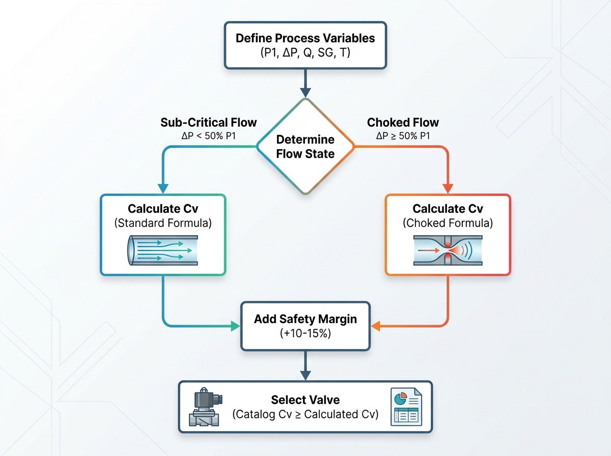
Compressible fluid dynamics dictate strict implementation realities. You cannot simply plug arbitrary numbers into a basic formula. You must first determine your exact flow state. Gases behave differently depending on the pressure differential across the valve.
Follow this step-by-step sizing approach to ensure accuracy:
By following these steps, you isolate the exact mathematical capacity required. You account for compressibility limits. You also protect your system against real-world degradation by applying logical safety margins.
You now have your calculated, safety-buffered Cv. You must transition from theoretical math to a physical valve selection. This requires navigating manufacturer catalogs carefully.
The golden rule of catalog mapping is straightforward. Look at the manufacturer data and select the next highest standard Cv rating available. If your calculated requirement is 2.1, and the catalog offers 1.5, 2.5, and 3.0, you select the 2.5 Cv model. Selecting the 1.5 model causes starvation. Selecting the 3.0 model invites control instability.
Engineers often confuse pipe connection threads with internal flow capacity. The internal orifice, known as the valve port size, dictates the actual flow limit. Connection threads like NPT or BSP merely connect the valve body to your piping. It is completely normal to install a valve possessing a smaller port size than the surrounding pipe. You simply utilize standard reducing fittings to make the physical connection.
Your internal architecture choice dictates performance boundaries. Direct-acting valves use electro-magnetic force to physically lift the seal. They are ideal for zero pressure drop environments or vacuum applications. However, their port sizes typically run smaller, limiting maximum flow. Pilot-operated valves use the line fluid pressure to open a larger diaphragm. They require a minimum pressure drop to keep the valve open.
If you select an oversized pilot valve, it will lack the required differential pressure to remain open fully. The diaphragm will lift, pressure will equalize immediately due to the oversized port, and the valve will slam shut. This causes rapid cycling, violent chattering, and eventual mechanical failure. Validate your architecture choice against your continuous pressure differential.
Valve Architecture Comparison Chart
| Feature | Direct-Acting Configuration | Pilot-Operated Configuration |
|---|---|---|
| Minimum Pressure Drop Required | 0 psi (Works in vacuums) | 5 to 15 psi (Brand dependent) |
| Flow Capacity (Cv Range) | Generally lower limits | Generally higher capacities |
| Primary Application Environments | Low pressure, small flow lines | High flow, high pressure mains |
| Failure Risk if Grossly Oversized | Wasted capital expenditure | Severe chattering, failure to open |
Even experienced process engineers stumble during component selection. Small miscalculations amplify into major process disruptions. Avoid these common traps to ensure your system runs smoothly.
Proper gas solenoid selection demands a sequential, mathematical process. You must define your core variables accurately without relying on assumptions. You then determine the flow state, evaluating if the gas acts sub-critically or hits choked flow limits. From there, you calculate the required theoretical Cv. Finally, you select a matching internal orifice capacity from the manufacturer catalog.
Do not guess or assume line sizes equate to internal flow capacity. For your next evaluation stage, take actionable steps. Utilize dedicated manufacturer sizing calculators to verify your manual hand-calculations. Cross-reference your mathematical results against official flow curve charts provided by the vendor. Lastly, consult an application engineer to confirm material compatibility between the valve elastomers and the specific gas you plan to control.
A: Cv represents the imperial standard, measuring US gallons per minute of water at a 1 psi pressure drop. Kv serves as the metric equivalent, measuring cubic meters of water per hour (m³/h) at a 1 bar pressure drop. You can easily convert between them using a simple multiplier. The formula is Cv = 1.156 × Kv.
A: No, doing this is physically dangerous and highly inaccurate. Liquids are generally incompressible, meaning their density remains constant regardless of pressure changes. Gas is highly compressible. As gas moves through an orifice and loses pressure, it expands and accelerates. Liquid formulas ignore expansion factors, leading to severely undersized gas valves.
A: Industry benchmarks normally recommend an allowable pressure drop of about 10% of the absolute inlet pressure. This provides a good balance between minimizing energy loss and keeping the physical valve size affordable. However, you must ensure this 10% drop does not unnecessarily trigger a choked flow condition for your system.
A: Temperature directly impacts gas density. Higher temperatures cause gases to expand, decreasing their overall density. This means you have less mass flow for a given volume. To pass the same required mass of hot gas compared to cold gas, you need a larger orifice. Consequently, higher operating temperatures dictate a larger required Cv.