lucy@zlwyindustry.com
+86-158-1688-2025
Please Choose Your Language
- All
- Product Name
- Product Keyword
- Product Model
- Product Summary
- Product Description
- Multi Field Search

Views: 0 Author: Site Editor Publish Time: 2026-07-25 Origin: Site


Precision dictates success in heavy industrial heating. You simply cannot guess thermal requirements when outfitting a boiler. Incorrect industrial burner sizing triggers compounded operational failures across your entire facility. Undersize the equipment, and you face the immediate inability to meet peak process loads. Oversize it, and you trigger violent short-cycling. This leads to accelerated refractory wear and severe thermal inefficiency.
A correctly sized unit perfectly matches your facility's heat load profile. It effortlessly accommodates fuel-specific properties. It maintains optimal turndown ratios. It also ensures full compliance regarding local emissions regulations. This guide provides a transparent, engineering-based framework to solve these challenges. We outline the strict steps needed for accurate capacity calculation. You will learn how to evaluate various atomization technologies. We also explain how to define precise technical specifications for vendor shortlisting. Following this framework ensures your next combustion equipment upgrade delivers reliable, lasting performance.
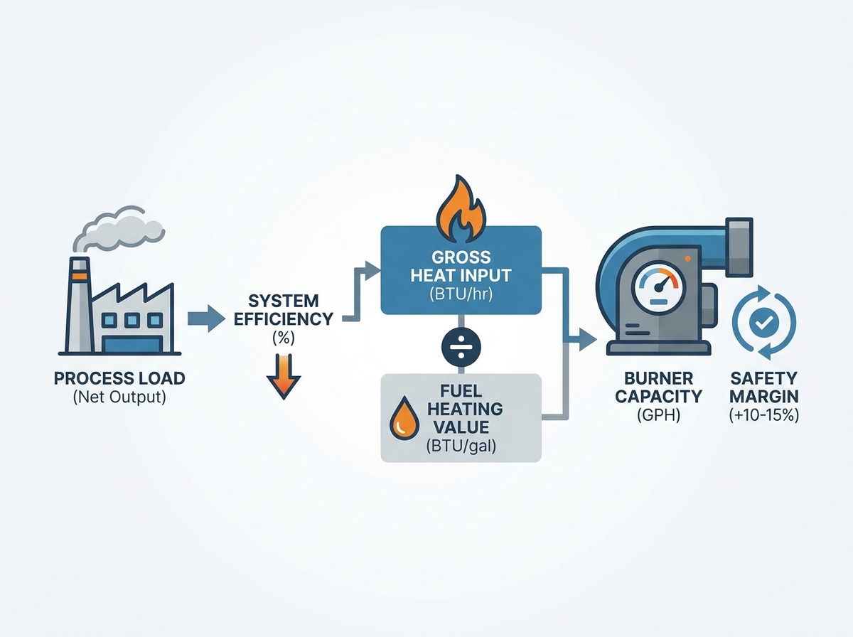
Procurement teams frequently confuse a boiler's output requirement with the burner's input requirement. This represents a fundamental error. You must size combustion equipment for the gross input. The burner supplies total thermal energy before appliance losses occur. Do not rely solely on the boiler horsepower or steam output ratings.
You must establish a baseline mathematical formula. First, determine the required steam or water output. Then, factor in the specific appliance efficiency.
For example, a boiler needs to produce 10,000,000 BTU/hr of steam. The vessel operates at 80% efficiency. You divide 10,000,000 by 0.80. The boiler heat input must therefore be 12,500,000 BTU/hr.
Next, you calculate the required flow in Gallons Per Hour (GPH). Translate the gross input into a specific fuel flow rate. Exact calculations require knowing the precise heating value of your chosen fuel. Standard No. 2 Fuel Oil yields approximately 138,000 to 140,000 BTU per gallon.
An accurate oil burner capacity calculation follows this equation:
Using our previous example, divide 12,500,000 BTU/hr by 140,000 BTU/gal. The application requires approximately 89.3 GPH of No. 2 oil.
Finally, apply standard engineering safety margins. Engineers typically add a 10% to 15% safety factor. This buffer compensates for piping heat loss. It also absorbs unexpected peak process demands. Avoid excessive padding. Adding a 30% margin guarantees chronic equipment short-cycling.
Successful furnace burner sizing is strictly constrained by physics. The firing head dictates the resulting flame geometry. The flame length and width must fit perfectly inside the existing chamber. The flame must never contact the vessel walls. Industry professionals call this flame impingement. Flame impingement cools the combustion reaction prematurely. It creates heavy carbon deposits. It also causes localized overheating. This eventually leads to catastrophic tube or refractory failure.
Evaluate the system’s static pressure next. Draft and backpressure limits define your blower requirements. The burner fan must overcome the internal draft resistance. It pushes air through the heat exchanger passages. It navigates the stack. It also pushes through any downstream economizers. Insufficient fan pressure causes incomplete combustion. It creates severe sooting.
You must also account for environmental derating. Standard ratings assume sea-level operation at standard temperatures. Real-world conditions vary significantly.
Equipment size cannot rely on peak load calculations alone. You must map the facility load profile. Assess facility demand fluctuations thoroughly. Does the plant run a steady 24/7 baseload? Do you manage volatile batch processing? A constant load tolerates simpler equipment. Variable batch processing demands highly flexible thermal input.
Understand turndown ratio economics. Define your application's turndown requirement. This is the ratio of maximum to minimum burner firing rate. A high turndown ratio measures 8:1 or 10:1. This means a 10 MMBTU unit can modulate down to 1 MMBTU.
High turndown minimizes destructive on/off cycling. Every single cycle requires a mandatory pre-purge sequence. The fan blows cold ambient air through the hot heat exchanger. This vents valuable thermal energy directly out the stack. High turndown drastically reduces this purge-cycle heat loss. It eliminates unnecessary fuel waste. It also reduces mechanical wear on the burner motor and ignition assemblies.
Evaluate modulation versus basic on/off controls. Basic high/low systems offer cheap upfront pricing. They fail spectacularly in volatile load environments. For heavy industrial applications, choose fully modulating burners. Fully modulating systems utilize parallel positioning. They often feature linkageless servomotor controls. These advanced controls yield superior return on investment. They maintain tight air-to-fuel ratios across the entire firing curve.
Different fuel grades require entirely different handling systems. Fuel viscosity directly dictates equipment selection. Light oils, like No. 2 diesel, flow easily at ambient temperatures. They atomize readily under standard pump pressures.
Heavy oils, including No. 4 and No. 6, behave differently. They possess high viscosity. They resemble thick syrup at room temperature. Heavy oils require dedicated pre-heating stations. You must install heat-traced piping. These additions ensure the fuel achieves combustible viscosity before reaching the nozzle. These auxiliary heaters create parasitic power loads. You must calculate these loads during facility electrical planning.
You must also select the correct atomization method. Atomization breaks liquid fuel into microscopic droplets. Smaller droplets ensure complete, clean combustion. Different technologies produce different outcomes.
| Atomization Method | Primary Mechanism | Ideal Fuel Types | Key Advantages | Main Limitations |
|---|---|---|---|---|
| Pressure Atomization | High-pressure mechanical pump forces fuel through a restricting nozzle. | Light oils (No. 2 fuel oil). | Cost-effective. Mechanically simple. Easy to maintain. | Limited turndown ratio (typically 3:1 max). Sensitive to viscosity changes. |
| Air Atomization | Compressed air shears the fuel stream into a fine mist. | Light and medium oils. Variable viscosity fuels. | Excellent turndown (up to 10:1). Very clean combustion. | Requires a dedicated, reliable compressed air source. Higher initial complexity. |
| Steam Atomization | High-pressure plant steam shatters heavy fuel droplets. | Heavy oils (No. 6 fuel oil). Very large industrial capacities. | Handles the thickest fuels effortlessly. Exceptional large-scale stability. | Consumes 1-3% of the boiler's own steam output. High parasitic loss. |
Review the specific process requirements. Pressure atomization suits smaller, steady-load applications using light oil. Air atomization provides superior flexibility for variable batch loads. Steam atomization remains the standard for massive utility boilers burning residual heavy oil.
Sizing decisions directly impact local emissions. Larger units routinely trigger stricter regulatory thresholds. The EPA and local air quality boards monitor Nitrogen Oxides (NOx), Carbon Monoxide (CO), and Sulfur Oxides (SOx).
Exceeding specific input thresholds changes your compliance category. Low-NOx designs often require much larger physical footprints. Many utilize Flue Gas Recirculation (FGR) systems. FGR pipes inert exhaust gas back into the combustion zone. This lowers the peak flame temperature. It drastically reduces thermal NOx formation. However, FGR requires larger blower motors to handle the increased gas volume. This alters your entire electrical sizing strategy.
You must adhere to NFPA 85 standards. The Boiler and Combustion Systems Hazards Code mandates strict safety protocols. Ensure the calculated capacity complies with these codes. Your selected fuel train must meet precise valve and venting requirements. NFPA 85 dictates safety shutoff valve placement. It determines purge timing calculations. Never compromise code compliance for a lower initial purchase price.
Consider retrofit compatibility carefully. Replacing a firing head on an existing furnace poses unique risks. Verify the existing fuel delivery loop immediately. Check the existing pumps. Measure the pipe diameters. Inspect the filtration systems. They must support the newly calculated flow requirement. Forcing 150 GPH through pipes sized for 80 GPH creates severe friction. This causes pump cavitation. Cavitation destroys fuel pumps and interrupts the combustion process.
Procurement must evaluate vendors through a strict engineering lens. Do not accept generic marketing claims. Demand specific performance guarantees based on your unique load profile.
Ask hard questions about efficiency claims. Vendors often base efficiency numbers on optimal, tightly controlled lab conditions. Real-world industrial environments operate differently. Dust, altitude, and fluctuating fuel quality degrade performance. Demand field-verified case studies. Furthermore, evaluate aftermarket support. Do they employ local commissioning technicians? Do they stock critical spare parts nearby? Extended downtime ruins facility profitability.
Prepare a robust Request for Quotation (RFQ). Vague RFQs yield inaccurate vendor proposals. You must build a comprehensive data package. Send this exact package to every shortlisted vendor.
Providing this exact list prevents assumptions. It forces vendors to quote equivalent, customized solutions.
Industrial burner sizing demands precise execution across multiple engineering disciplines. You must balance mathematical heat input requirements against physical chamber constraints. Environmental factors drastically alter equipment performance and necessitate careful derating calculations. Properly mapping your facility load profile ensures you select the correct turndown ratio, ultimately preventing destructive short-cycling. Finally, proactive collaboration remains your strongest tool. We strongly recommend procurement teams partner directly with combustion engineers or OEM technical representatives. They will rigorously validate your baseline calculations before you finalize any heavy capital expenditures.
A: Oversizing forces the equipment to shut off and restart frequently. Engineers call this short-cycling. Every single restart requires a mandatory pre-purge cycle. The fan blows cold ambient air through the hot heat exchanger. This vents valuable thermal energy straight out the stack. It significantly degrades overall thermal efficiency and increases fuel costs.
A: The foundational heat input formula remains identical across fuels. However, you cannot use gas formulas for final sizing. Volumetric fuel calculations differ entirely. Combustion air requirements change based on fuel density. Furthermore, the physical flame envelopes differ drastically. Oil flames typically require different chamber dimensions than gas flames.
A: Engineers typically add a 10% to 15% safety margin to the baseline calculated load. This specific buffer accounts for piping heat losses. It absorbs minor equipment degradation over time. It also handles sudden operational spikes. However, safety margins exceeding 20% create immense risk. They almost guarantee chronic, destructive short-cycling.