lucy@zlwyindustry.com
+86-158-1688-2025
Please Choose Your Language
- All
- Product Name
- Product Keyword
- Product Model
- Product Summary
- Product Description
- Multi Field Search

Views: 0 Author: Site Editor Publish Time: 2026-08-03 Origin: Site


Operating an obsolete Burner Management System (BMS) carries compounding risks for any industrial facility. Plant managers face severe part scarcity, undocumented lockout codes, and sudden unplanned downtime. You simply cannot afford to let aging logic boards dictate your production schedule. When critical heating equipment fails, entire manufacturing lines grind to a halt. However, swapping out an outdated unit is rarely a simple plug-and-play operation. It requires you to navigate complex voltage differences, modern safety interlocks, and severely degraded wiring systems.
We built this comprehensive guide to help you manage these exact hurdles. This article provides facility managers and stationary engineers an evidence-based roadmap for executing a legacy burner controller replacement. You will learn how to ensure seamless equipment integration, avoid common installation pitfalls, and achieve compliant, safe restarts.
Defining the operational tipping points justifies capital expenditure on burner controls. Facility operators must identify when minor repairs become unsustainable liabilities. Aging electronic components eventually demand a decisive strategy shift. You must frame this business problem around reliability, facility safety, and production uptime.
You should watch for specific hardware indicators before proceeding. Evaluate these warning signs carefully to determine if an upgrade is necessary:
Operators often struggle to choose the correct upgrade path. Sometimes a focused panel upgrade suffices. Other situations demand comprehensive mechanical overhauls. We developed a decision matrix to clarify this crucial choice.
| Upgrade Strategy | Ideal Technical Scenario | Primary System Drivers |
|---|---|---|
| Controller-Only Swap | Physical burner, valves, and mechanical linkages remain in peak condition. | The core logic board fails frequently, but actuators and fuel lines operate flawlessly. |
| Full burner controller retrofit | Existing servomotors, fuel trains, or draft controls cannot accept digital signals. | Modern microprocessors demand precise inputs. Aging mechanical parts fail to meet these tolerances. |
Transparency remains vital during this early planning phase. A localized electronics swap will not fix underlying mechanical inefficiencies. You cannot cure warped burner heads by installing a new logic processor. A new panel cannot repair failing gas regulators or leaking valves. Evaluate your entire mechanical train honestly before buying new electronics. Upgrading a microprocessor on a failing mechanical rig wastes capital and extends frustration.
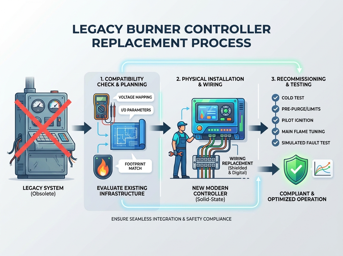
Proper technical evaluation mitigates major project risks early. You must audit the current setup thoroughly to prevent mid-project scope creep. Many engineering teams underestimate how legacy hardware interacts alongside modern microprocessors. Skipping this audit leads to costly delays.
First, examine the sub-base and physical footprint. Evaluate if the new controller requires an adapter base. Sometimes, you need a completely new panel layout to accommodate modern dimensional standards. Do not assume your new unit will easily snap into a 30-year-old mounting bracket. Physical dimensions vary wildly between generations of hardware.
Input and Output (I/O) parameter checks represent the most critical audit phase. Ensuring controller compatibility with existing flame safeguards is mandatory. For example, UV scanners function very differently from older IR sensors. Solid-state controllers often require specific scanner amp draws to register a flame safely. You must read the manufacturer datasheets closely to match these values.
You also need precise voltage mapping. Converting legacy 120V pilot signals to 24V modern equivalents requires careful electrical planning. You might need specific step-down transformers to handle these signal conversions. Ignoring these voltage differences will destroy your new solid-state boards instantly upon power-up.
Next, assess the main wiring harness thoroughly. Reusing 30-year-old brittle wire is a dangerous false economy. Heat degrades insulation over time. This exposes bare copper and causes random short circuits. You must establish strict criteria for mandatory wiring replacement. Look for heavy insulation degradation or a lack of shielding. Modern digital communication lines demand properly shielded cables. Unshielded wires invite electromagnetic interference, causing phantom lockouts on new processors.
Navigating implementation realities requires managing stakeholder expectations effectively. Your boiler or furnace will experience unavoidable offline time. You must communicate these schedules clearly to production and facility teams. Solid preparation prevents unexpected operational delays and lost revenue.
Data baseline capture is an absolutely essential preliminary step. You must document existing combustion curves, draft settings, and physical linkage positions. Do this before dismantling any legacy unit components. If you lose this baseline, tuning the new system becomes incredibly difficult. Take high-resolution photographs of all mechanical linkages. Record exact actuator degrees at low-fire and high-fire positions. This data serves as your roadmap for recommissioning.
Staging and component sourcing also protect your installation timeline. Always have parallel components on hand before beginning the shutdown. Stock extra fuses, replacement terminal blocks, and spare flame scanners. Having these available prevents painful 48-hour delays over minor incompatible parts. A missing fifty-dollar relay should never halt a massive capital project.
Finally, standardize your safety tag-out and lock-out (LOTO) protocols. You must isolate fuel lines and main electrical feeds completely. Strict adherence to LOTO procedures protects your engineers during the physical changeover. Double-check all manual gas valves for leak-through. Never cut corners when isolating heavy industrial fuels, as the consequences can be catastrophic.
Bringing the new equipment online safely requires a rigid, actionable framework. You need a sequential guide to ensure safety limits activate properly. Do not rush this critical phase. We recommend following a strict five-step process for every upgrade to guarantee optimal safety.
Skipping any of these steps compromises facility safety severely. Strict adherence protects personnel and prevents catastrophic combustion failures. Do not allow production pressures to rush your commissioning sequence. Safety always supersedes the manufacturing schedule.
Transitioning from a mechanical success to full regulatory compliance demonstrates true operational authority. You must prove the new setup operates securely. Proper documentation builds absolute trust with stakeholders, jurisdictional inspectors, and insurance providers. A successful installation means nothing without the paperwork to back it up.
Start by generating a comprehensive commissioning report. You must include final combustion readings across all firing rates. Document the specific flame signal strength during both pilot and main flame operation. Record all simulated fault test results clearly. Good documentation provides a reliable baseline for future troubleshooting.
Code compliance remains non-negotiable for industrial thermal systems. You must ensure the new setup satisfies local jurisdictional inspectors. Modern safety standards, such as NFPA 85 or NFPA 86, require specific interlock responses and valve proving sequences. The insurance underwriters will demand proof of these safety verifications before certifying the boiler room. A failed inspection extends your costly downtime unnecessarily.
Operator training finalizes the upgrade process successfully. Brief the facility team on the new human-machine interface (HMI). Walk them through common fault codes and proper reset procedures. A well-trained operator prevents dangerous user-error lockouts. They must understand what the new screen tells them before repeatedly hitting the reset button. Ignorance at the control panel negates the benefits of your new hardware.
Conclusion
Replacing a legacy controller bridges the dangerous gap between aging mechanical equipment and modern safety standards. It restores reliability to your critical heating processes while ensuring strict code compliance. Do not wait for a catastrophic logic failure to force your hand. Upgrading now eliminates the frantic search for obsolete relays and mitigates unexpected downtime. Modern systems provide deeper diagnostics, saving your maintenance team countless hours of blind troubleshooting.
Your next steps require decisive action and planning. Encourage your leadership to schedule a professional site audit immediately. Have a qualified technician map your existing panel to specify the correct replacement components. Proactive planning today guarantees a seamless, safe operational transition tomorrow. Secure your production schedule by modernizing your burner controls before obsolescence strikes.
A: It usually takes one to three days. The exact timeframe depends on whether a full wiring replacement is required. If the existing wire harness remains intact and the recommissioning process goes smoothly, technicians can often complete the swap in a single shift.
A: Yes, you can achieve this through proper retrofitting. However, it requires verifying compatibility with your existing flame scanners and mechanical actuators. You may need to install specific amplifiers or upgrade analog servomotors to accept modern digital signals reliably.
A: Improper wiring termination frequently causes early lockouts. Mismatched flame scanner microamp requirements also trigger false failures. Additionally, modern air-proving switches feature overly sensitive tolerances compared to legacy systems, which can cause nuisance tripping until properly adjusted.