lucy@zlwyindustry.com
+86-158-1688-2025
Please Choose Your Language
- All
- Product Name
- Product Keyword
- Product Model
- Product Summary
- Product Description
- Multi Field Search

Views: 0 Author: Site Editor Publish Time: 2026-08-12 Origin: Site


You pull a component, ground it against the block, and crank the engine. A bright arc jumps across the gap immediately. You naturally assume the system works perfectly. You reinstall the component, however, and the engine immediately misfires. This frustrating diagnostic trap catches many technicians completely off guard.
A spark firing in ambient air faces minimal electrical resistance. Inside a sealed cylinder, extreme pressure and rich fuel mixtures drastically multiply this electrical resistance. A compromised system pushes a weak arc through open air easily. It simply lacks the raw voltage reserves required for heavy operational demands.
We will explore the exact physics behind this hidden mechanical failure. You will discover a measurement-first diagnostic framework to isolate the root cause accurately. Stop needlessly replacing expensive coils and control modules based on visual guesswork. Learn how to pinpoint the exact failure point today.
You open the throttle fully. The cylinder pressure rises rapidly. This high pressure packs air and fuel molecules tightly together. The electrical arc must push through this extremely dense physical barrier. It requires exponentially more voltage to ionize the gap under these harsh conditions. This specific physical reality creates a weak ignition spark under load.
We must understand the difference between available voltage and required voltage. Available voltage represents what the coil can theoretically produce. Required voltage dictates what the gap actually demands to fire. A healthy system produces around 40,000 volts total. Normal idling might only demand 10,000 volts. The remaining 30,000 volts act as a crucial reserve. A failing system loses this reserve capacity entirely. It fires perfectly at idle but collapses under pressure.
You will typically observe several common symptoms. Engines misfire exclusively during heavy acceleration or hill climbing. You might experience rough idling when activating heavy electrical accessories. Industrial setups often exhibit clicking noises. They fail to cross-ignite properly despite producing an audible firing sound.
You must discard the visual eyeball test immediately. Relying on arc color remains an outdated diagnostic myth. Blue sparks and yellow sparks both fail to quantify actual electrical output. A seemingly healthy blue arc can still lack the necessary amperage to ignite dense mixtures.
You need an adjustable inline spark tester. This tool simulates heavy load conditions outside the combustion chamber. You connect the tester inline between the coil and the ground source. Widening the physical gap forces the coil to output maximum voltage. Set the tester gap to roughly one-half inch. Crank the engine over. The system should consistently jump this wide gap in open air. This proves it possesses adequate reserve voltage for high-pressure environments.
Next, you must test the internal windings. Grab a high-quality digital multimeter. Perform a comprehensive ignition transformer test using the Ohms setting. Measure the primary and secondary resistance circuits separately. Compare your measured values directly against manufacturer specifications.
Testing presents a significant implementation risk regarding temperature. You might test components while they are completely cold. Heat expands microscopic internal winding breaks. A cold coil often tests perfectly normal. It only opens the circuit when reaching operating temperature. Always test suspect components after they reach full operating heat.
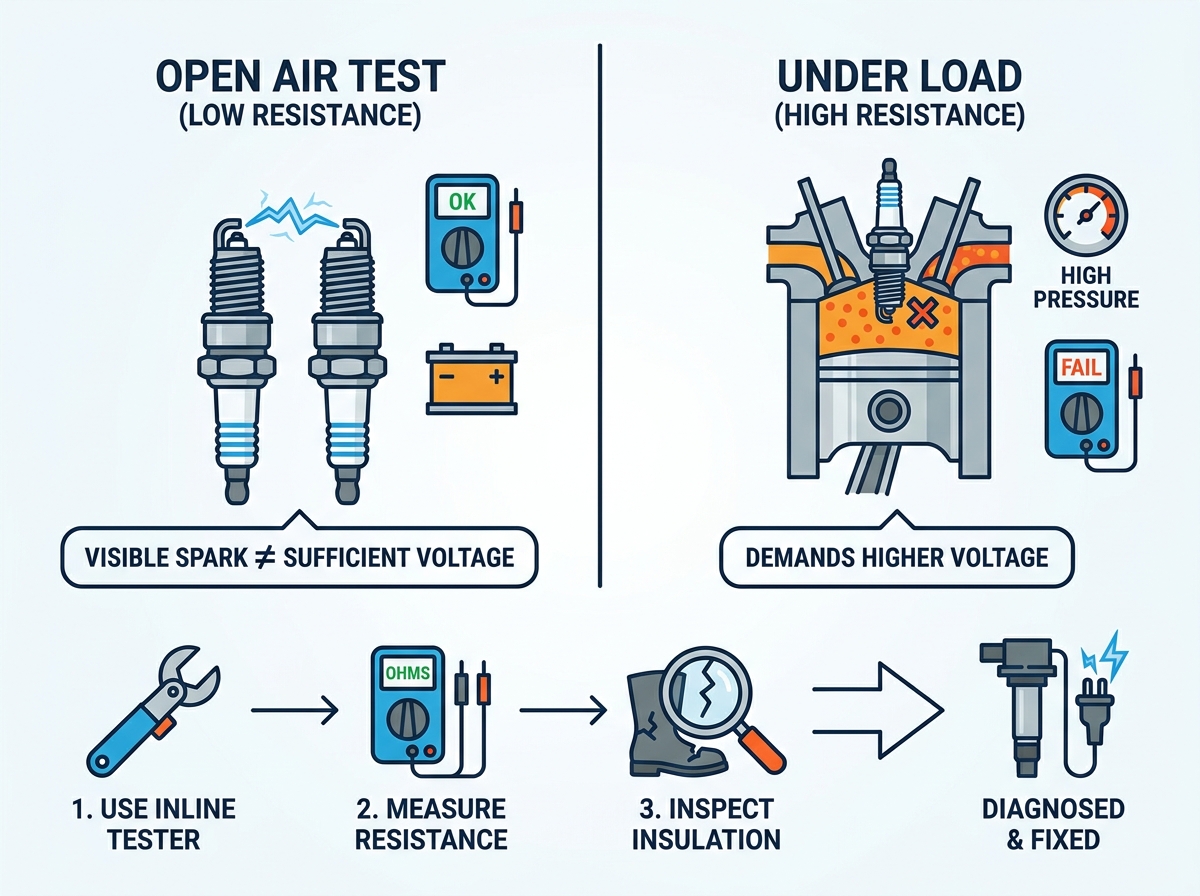
Electricity aggressively seeks the easiest path to ground. Gap resistance spikes dramatically under heavy throttle loads. The current looks for alternative routes to escape. This uncontrolled electrical detour causes severe spark leakage. The energy never reaches the designated firing tip.
You must visually inspect all components for these leaks. Examine the white ceramic surfaces closely. Look for faint black zigzag lines tracing down the sides. We call this phenomenon carbon tracking. Check all high-tension cords thoroughly. Look for tiny pinhole burns or brittle rubber sections. These indicate where high voltage escapes the intended circuit.
Dielectric breakdown ruins system integrity over time. Moisture ingress destroys internal component barriers. Valve cover oil leaks often submerge components entirely. General age turns flexible rubber boots rock hard. These harsh factors degrade the electrode insulation rapidly. The voltage bleeds directly into the metal engine block before ever crossing the firing gap.
You can verify this failure using a simple method. We call it the dark room water mist test. Turn off the garage lights completely. Start the engine and let it idle. Spray a very fine water mist over the running components. Watch carefully for blue arcs dancing along the wires or boots. Any visible light indicates a severe breach in the protective casing.
Technicians often encounter a frustrating false positive. You test the coil resistance accurately. The values look absolutely perfect. The exterior casing remains completely intact. Yet, the system still misfires violently under compression. You must look beyond the coil itself.
You need to perform voltage drop testing on the power circuits. The coil requires full battery voltage to saturate its magnetic field properly. Test the power delivery wire while the circuit operates. Next, test the main chassis ground circuit thoroughly. A poor ground connection severely limits primary current flow. If the coil cannot saturate fully, it cannot release a strong secondary pulse.
Trigger and timing interruptions also cause load failures. Evaluate the Crankshaft Position Sensor signals. Check the ECU trigger commands using an oscilloscope. A weak or erratic pulse prevents full saturation time. This delivers a remarkably weak arc exactly when engine demand peaks. The coil itself works fine. The controlling computer simply fails to command it correctly.
These diagnostic principles apply directly to heavy industrial equipment. HVAC setups, commercial boilers, and industrial furnaces face identical physical challenges. A weak burner spark creates dangerous situations. It often causes explosive delayed ignitions. It frequently triggers frustrating safety lockouts during cold weather starts.
Burner systems introduce unique environmental variables. Draft variations alter the electrical resistance inside the firing tube. High airflow velocity literally blows the arc away from the fuel source. Lean fuel-air mixture ratios dictate higher voltage demands. You must account for these dynamic variables during your diagnosis.
Testing requires extreme caution in these settings. Industrial units typically generate well over 10,000 volts. You cannot safely test these units inside the active firing chamber. Assess the igniter rod positioning carefully while the unit remains powered down. Verify grounding integrity within the burner assembly shell. A rusted mounting bracket often ruins the necessary ground path.
Deciding what to replace requires analyzing your test data objectively. Do not throw arbitrary parts at complex electrical problems. Follow a structured decision matrix to save money and time.
You should replace wires and plugs only under specific conditions. The primary control module passes all resistance checks. You observe visible carbon tracking on the ceramic casing. Always replace these items as a perfectly matched pair. Installing a new plug inside an old, carbon-tracked boot guarantees immediate failure. The old track will instantly destroy the new ceramic casing.
You must replace the main transformer when secondary resistance falls out of specification. You also replace it if the adjustable inline tester fails the simulated load gap test. This confirms internal winding degradation. The component simply cannot generate enough magnetic force anymore.
Investigate sensors and ECU modules last. You do this when all secondary components test perfectly. The primary circuit fails to ground or trigger correctly under active load conditions. This points to logic failures rather than raw power failures.
Follow these sequential diagnostic steps:
Diagnostic Decision Matrix
| Component Status | Load Test Result | Recommended Action |
|---|---|---|
| Resistance normal, visual carbon tracking present | Passes open air, fails under load | Replace plugs and boots as a matched set. |
| Secondary resistance out of spec | Fails 1/2-inch gap test | Replace the coil or main transformer unit. |
| Resistance normal, no visual tracking | Fails 1/2-inch gap test | Check primary voltage drop and chassis ground. |
| All resistance normal, grounds verified | Intermittent firing under load | Test crankshaft sensor and ECU trigger signals. |
Diagnosing load-based failures requires shifting away from visual assumptions. You must embrace measured electrical realities. High cylinder pressure reveals weaknesses you cannot see in ambient air. Multimeters and adjustable gap testers are your most reliable diagnostic tools.
Always verify your repairs meticulously. Recreate the exact load conditions you experienced initially. Test drive the equipment under heavy strain or high airflow velocity. A repair remains incomplete until it survives peak operational stress.
Consult your OEM service manuals for specific resistance values. Use professional diagnostic equipment to simulate loads safely. Upgrade your replacement components to match the demanding physical realities of your specific equipment.
A: High pressure and compressed fuel mixtures create electrical resistance. A weak coil can generate enough voltage for ambient air (low resistance) but lacks the power to bridge the gap under cylinder pressure.
A: You cannot safely test it inside the firing chamber. Instead, use a multimeter to check winding resistance, or use a high-voltage testing probe/adjustable gap tester to simulate the operational load safely outside the unit.
A: Yes. A poor ground restricts the current flowing through the primary coil winding. If the coil cannot fully saturate with energy, the resulting secondary spark will be too weak to fire under compression.
A: Look for carbon tracking (faint gray/black lines) on the white ceramic insulator, micro-cracking, or chalky white residue inside the spark plug boot indicating voltage is leaking to the block.