lucy@zlwyindustry.com
+86-158-1688-2025
Please Choose Your Language
- All
- Product Name
- Product Keyword
- Product Model
- Product Summary
- Product Description
- Multi Field Search

Views: 0 Author: Site Editor Publish Time: 2026-07-29 Origin: Site


Industrial combustion inherently carries major, unyielding risks. One fundamental danger is relying on a safety shut-off valve which has mechanically failed but electronically signals as closed. This hidden vulnerability allows explosive fuel to silently pool inside a dark chamber. Unnoticed gas leakage into a combustion chamber during standby remains a primary cause of catastrophic boiler and furnace explosions worldwide. To combat this severe threat, modern engineering has aggressively shifted away from periodic manual leak detection. Instead, safety protocols now embrace automated, zero-trust verification systems.
A Valve Proving System (VPS) is not just an optional safety upgrade to make facility managers feel secure. It acts as a critical, code-mandated component for many specific industrial burner applications. By verifying valve integrity before ignition, these systems prevent catastrophic fuel accumulation. In the following sections, we will explore exactly how these systems operate. You will learn when stringent safety codes legally demand their installation. You will also discover how to practically evaluate retrofit options for your existing industrial facility.
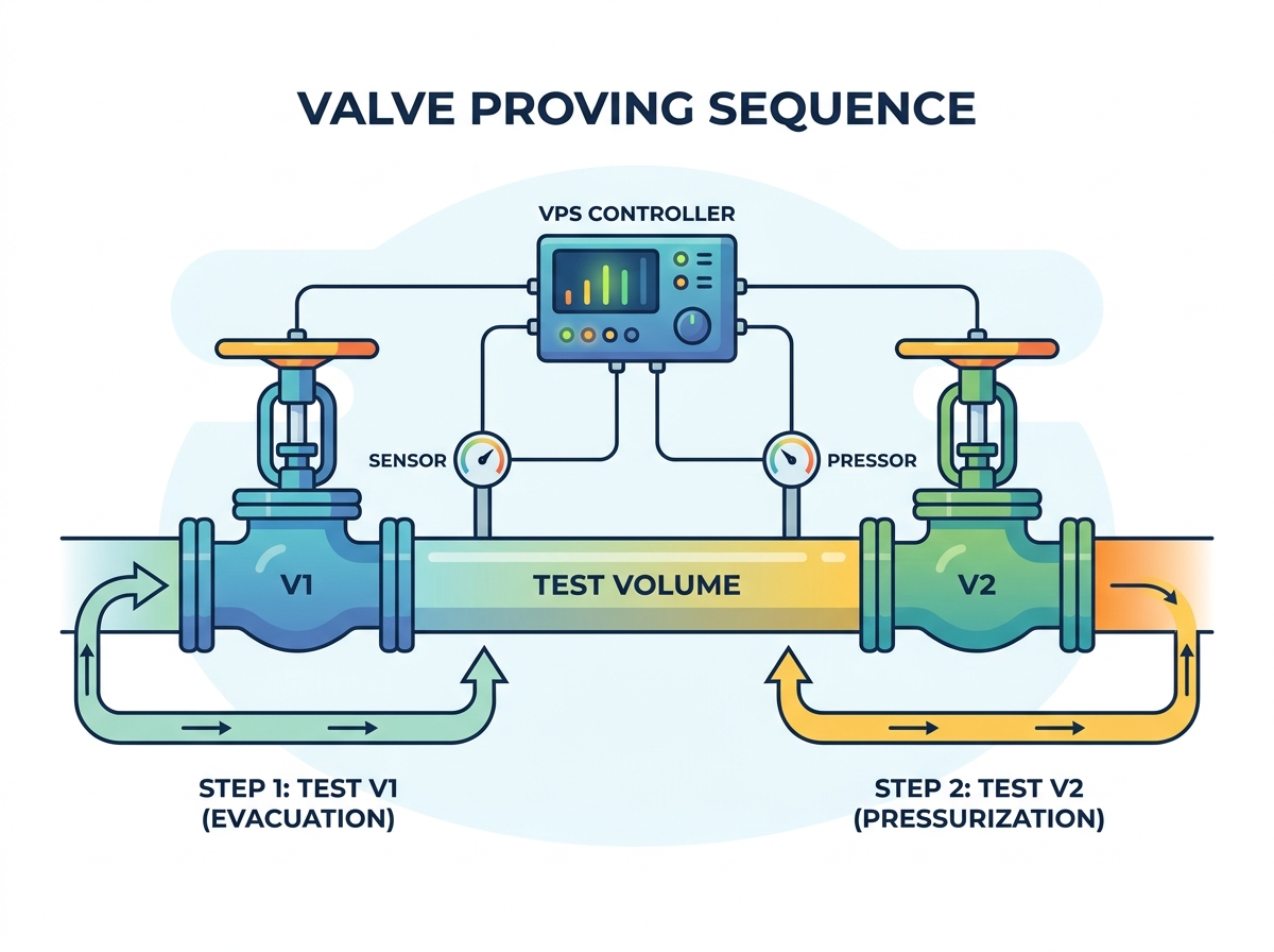
Demystifying the physical sequence helps establish true technical authority on combustion safety. The entire process relies on a "zero-trust" sequence checking a highly specific zone. We call this the test volume. The test volume is the isolated pipe space located directly between the upstream and downstream safety shut-off valves. You cannot simply assume these valves are sealed tight just because the controller removed power from them. A mechanical obstruction or worn seal can easily allow gas to seep through.
The system executes a precise logic sequence to test this isolated space. A properly configured valve proving system burner test removes all operational assumptions through two primary phases:
If any leak exceeds the programmed, permissible tolerance, the system triggers a hard alarm. It immediately locks out the burner ignition sequence. This lockout prevents a potentially lethal startup sequence from advancing.
Relying on subjective advice for safety equipment invites disaster. Burner size and regional safety codes dictate compliance requirements globally. Guidelines from authorities like the National Fire Protection Association (NFPA), CSA Group, and European Norm (EN) remove all guesswork from the equation.
Capacity thresholds act as the primary trigger for compliance mandates. Authorities outline specific rules based on the total thermal output of the equipment. For example, NFPA 85 governs boiler systems, while NFPA 86 oversees industrial ovens and furnaces. These standards mandate automated checking once burner capacities exceed certain thermal outputs.
Common Compliance Thresholds Overview
| Regulatory Standard | Application Type | Typical Trigger Threshold | Requirement Note |
|---|---|---|---|
| NFPA 85 | Boiler and Combustion Systems | Typically > 5 MMBTU/hr | Often requires verification for multi-burner systems. |
| NFPA 86 | Industrial Ovens and Furnaces | Typically > 400,000 BTU/hr | Strictly mandates automated checking for specific burner sizes. |
| EN 676 / EN 746 | European Burner Standards | > 1200 kW (approx. 4 MMBTU/hr) | Requires proving for large capacity gas burners globally adopting EN norms. |
| CSA B149.3 | Canadian Field Approval Standard | Variable by jurisdiction | Mandates testing for unattended or large-scale continuous processes. |
Application mandates go beyond mere capacity thresholds. We must consider continuous versus batch processing environments. Batch ovens cycle on and off frequently throughout a standard shift. This frequent cycling accelerates mechanical valve wear tremendously. Elevated wear drastically increases the operational need for an automated burner safety valve test. Unattended operations also carry strict parameters. Facilities running burners overnight without human supervision must rely on automated checks to ensure absolute safety.
Finally, insurance companies routinely mandate these installations regardless of municipal leniency. Commercial insurers frequently go beyond local municipal codes. They require these systems for large heating assets to minimize risk liability. Falling behind national standards exposes your facility to denied insurance claims following a catastrophic incident.
You must evaluate your current infrastructure carefully before selecting a solution category. Throwing modern technology at outdated piping often creates cascading issues. There are two primary deployment paths, each offering distinct advantages and limitations.
Standalone VPS Controllers
Integrated Burner Management Systems (BMS)
When selecting either path, keep these key evaluation dimensions in mind. Adjustable test times are crucial. You need the ability to accommodate different pipe volumes across various sized gas trains. NEMA or IP ratings remain essential for ensuring durability in harsh, dusty, or wet industrial environments. Lastly, scrutinize the diagnostic reporting capabilities. Does the system merely issue a generic failure code? Or does it pinpoint exactly which valve failed? Advanced diagnostics save your maintenance team hours of blind troubleshooting.
Retrofitting older equipment introduces distinct physical and operational hurdles. First, evaluate your gas train real estate carefully. You need adequate physical space to install pressure switches and test piping directly between your existing double block valves. Often, older, compact piping setups lack this necessary footprint. This deficiency requires you to execute extensive re-piping before adding the new electronics.
Calibration presents another harsh reality check. Setting the pressure switches properly is a meticulous, mathematical task. You must account for the exact volume of the pipe segment. Gas pressure, ambient temperature, and pipe diameter all impact the test. Incorrect test volume calculations routinely lead to nuisance trips. These false positives frustrate operators and stall production. Worse, poor calibration creates unsafe conditions by generating false negatives, essentially masking a real leak.
Expect specific downtime during installation and commissioning. You must lock out the system safely, purge all gas lines, pipe new fittings, wire the panel, and carefully commission the setup. Provide a realistic assessment for your facility stakeholders. This complete process usually sidelines a boiler or furnace for one to three full days. Careful planning with specialized combustion technicians mitigates this operational interruption.
Many facility managers object to automated upgrades. They often claim they already perform manual bubble tests during routine maintenance. However, this outdated approach has severe, undeniable limitations.
Manual bubble testing only verifies mechanical integrity at the exact moment of the test. Facilities typically run these tedious tests annually, or monthly at best. A valve seal could easily fail just two days after a manual inspection. This failure leaves the system completely vulnerable to gas pooling for weeks before anyone notices.
An automated VPS delivers continuous, reliable risk mitigation. It checks the safety valves every single time the burner fires or shuts down. It catches premature mechanical wear immediately. It stops the burner dead in its tracks before an explosion hazard ever develops inside the combustion chamber.
Transitioning from manual methods to automated systems drastically improves your operational efficiency. It directly contrasts ongoing labor costs and required facility downtime against a nearly instantaneous cycle. Your maintenance team saves countless hours skipping manual leak checks. Furthermore, human error completely disappears from the safety equation. Operators no longer have to interpret bubble sizes or guess if a valve seal feels secure.
A Valve Proving System remains the absolute most reliable bridge between mechanical valve vulnerability and safe burner operation. Relying solely on physical valve seals without electronic verification leaves facilities dangerously exposed to catastrophic risks. Mechanical parts wear out over time, and automated safety systems are the only way to catch those failures instantly.
Take these immediate steps to secure your facility:
A: A VPS is a specific subsystem dedicated to detecting gas leaks between safety shut-off valves. A Burner Management System (BMS) governs the entire ignition and combustion process, including purging, pilot ignition, and flame monitoring. A VPS can be a standalone unit or integrated directly into a modern BMS.
A: Yes, retrofitting is common. However, it requires adequate physical space to install the necessary pressure switches and test ports directly between the upstream and downstream safety shut-off valves. If space is tight, some piping modifications may be required.
A: The test typically takes between 10 to 60 seconds. The exact duration depends on the specific test volume size and the incoming gas pressure. This sequence happens invisibly during the standard pre-purge or post-purge cycle, minimizing operational delays.
A: A failure triggers when the system detects a pressure drop or rise that falls outside the legally permissible leak rate. This threshold is typically measured in liters per hour. If a valve allows gas to pass beyond this strict limit, the system locks out.