lucy@zlwyindustry.com
+86-158-1688-2025
Please Choose Your Language
- All
- Product Name
- Product Keyword
- Product Model
- Product Summary
- Product Description
- Multi Field Search

Views: 0 Author: Site Editor Publish Time: 2026-08-19 Origin: Site


It is incredibly frustrating when your burner management system (BMS) registers a "flame proven" signal during the ignition sequence, only to trip off seconds later. The igniter de-energizes, the fuel valves open, but the system immediately shuts down. This scenario goes beyond a simple nuisance trip. It reveals a fundamental flaw in flame discrimination. This flaw triggers continuous equipment lockouts, extends facility downtime, and increases the risk of unburned fuel accumulation inside the combustion chamber.
In this article, we provide a comprehensive diagnostic framework for engineers and facility managers. You will discover exactly why this error happens and how to identify the root causes. Furthermore, we will help you evaluate permanent, compliant solutions to restore safe, reliable burner operation in your facility.
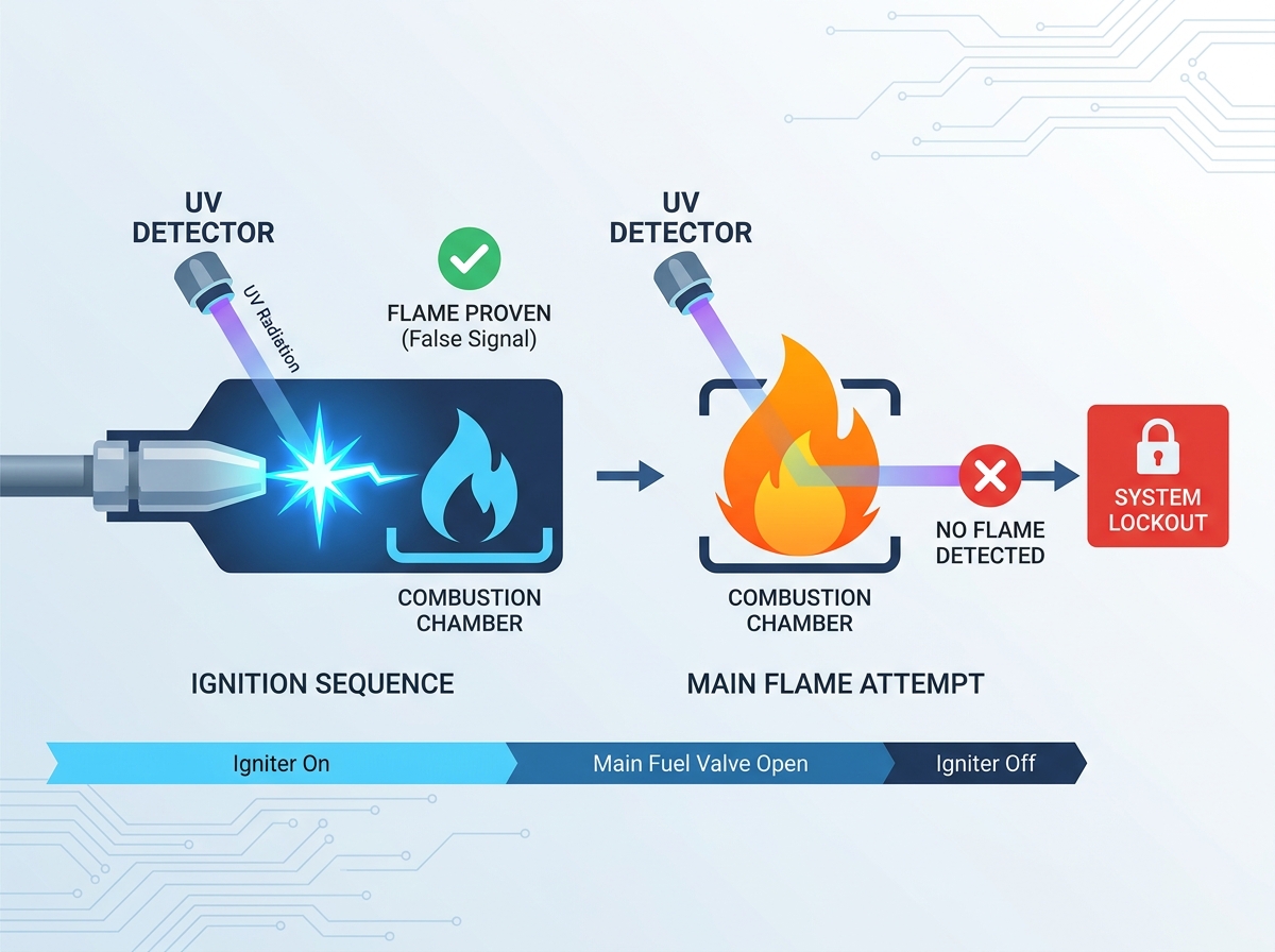
To understand why this malfunction occurs, we must look at how standard ultraviolet (UV) scanners detect radiation. Basic UV scanners operate by sensing light emissions in the 190 to 250-nanometer spectrum. When an ignition transformer creates a high-voltage electrical arc to light the fuel, that arc emits an intense burst of UV radiation. To a basic sensor, this high-energy arc looks exactly like a hydrocarbon combustion flame. This overlap in emission spectrums is the primary cause of a flame detector false signal during the start-up sequence.
When this happens, the burner management system executes a flawed logic sequence. We can map this lockout sequence to see exactly where the failure occurs:
Because the sensor loses its signal source the moment the spark ends, the BMS registers a sudden main flame failure. It immediately closes the safety shutoff valves, resulting in a hard, unavoidable burner lockout.
The business impact of these continuous trips is severe. Frequent lockouts create major production bottlenecks. Boiler downtime halts facility operations. Furthermore, repeated failed starts put immense wear-and-tear on ignition components, valves, and relays. You burn through consumable parts much faster than necessary.
Finding out why your flame detector sees ignition not main flame requires a methodical approach. The root cause usually falls into one of three categories: physical alignment, combustion dynamics, or sensor degradation.
Improper scanner sighting is the most common culprit. Industrial scanners view the combustion zone through a metal sighting tube. If technicians aim this tube directly at the igniter tip rather than the primary combustion zone, the scanner easily reads the spark. Over time, shifting burner geometry worsens this problem. High temperatures cause the burner front to undergo thermal expansion. This expansion slowly warps the sighting tube, skewing the sensor's line of sight directly toward the spark gap and away from the main flame envelope.
Combustion dynamics heavily influence what the scanner can see. Sometimes, high draft pressures or incorrect fuel-air mixtures push the main flame envelope away from the burner nozzle. We call this phenomenon "flame lift-off." When the flame root lifts away, it moves out of the scanner's viewing angle. However, the physical igniter remains fixed in place. During start-up, the scanner clearly sees the stationary spark, but it cannot see the lifted main flame once the spark extinguishes.
You must also consider the age and condition of your UV tubes. Standard UV tubes contain a specific inert gas mixture. As these tubes age, they degrade. Aging tubes often become overly sensitive. Sometimes, they experience a "runaway" condition. When the intense burst of the ignition spark hits them, the tube essentially becomes blinded. It fails to recover quickly enough from the intense UV saturation. By the time it resets, the BMS has already tripped the system offline.
Once you diagnose the exact cause, you can evaluate solutions. Fixes range from zero-cost physical adjustments to comprehensive technology upgrades. You must weigh the effort against the reliability gained.
If your budget is tight, start by adjusting the physical geometry of the installation.
If physical adjustments fail, consider upgrading the scanner head. Modern intelligent scanners feature advanced software and hardware designed specifically for ignition spark detection rejection. They use frequency filtering. An electrical arc pulses at a very rapid, specific frequency. A hydrocarbon flame flickers at a much slower, random frequency. Intelligent UV scanners differentiate between these two frequencies, actively ignoring the spark pulse and only verifying the true flame.
For the highest reliability, many engineers transition away from standalone UV technology entirely. Infrared (IR) sensors monitor the specific flicker of hot combustion gases, primarily carbon dioxide. Because an electrical arc does not emit hot CO2 gases, IR sensors are naturally blind to igniter sparks. For critical applications, dual-sensors (UV/IR) offer the best protection. They cross-reference both spectrums before verifying the main flame.
Remediation Strategy Comparison Chart
| Strategy | Relative Cost | Effectiveness | Best Application |
|---|---|---|---|
| Physical Alignment | Low | Moderate | Minor geometric shifts |
| Advanced UV Filtering | Medium | High | Clean gas applications |
| IR Technology | Medium-High | Very High | Oil/coal, heavy draft |
| Dual-Sensor (UV/IR) | High | Maximum | Complex multi-burner |
Deciding to upgrade your sensing technology is only the first step. You must carefully navigate the implementation phase to ensure success. Upgrading safety instruments introduces specific rollout risks.
Upgrading sensors requires a complete burner shutdown. You must pull new wiring, install different scanner bases, and potentially reprogram the BMS logic. You need to carefully assess the operational cost of this installation downtime. Compare this pause against the ongoing pain of continuous nuisance trips. Usually, scheduling a planned outage for an upgrade is far better than suffering unpredictable, emergency shutdowns during peak production.
Do not expect modern scanners to work perfectly right out of the box. Advanced scanners require precise tuning during commissioning. Technicians must adjust the gain, set the specific flicker frequency, and establish proper threshold settings. If you skip this critical step, the new scanner might swing from one extreme to another. It could go from generating a false positive to completely failing to detect a healthy flame. Proper tuning ensures the scanner operates exactly as intended.
Safety must remain your top priority. Any change in your flame detection strategy must strictly adhere to local boiler codes. In North America, you must follow NFPA 85 standards for boiler and combustion systems. In Europe, EN 746-2 dictates the rules for industrial thermoprocessing equipment. Furthermore, ensure your new hardware maintains the required Safety Integrity Level (SIL) ratings for your specific facility. Never bypass a safety relay just to force a burner to start.
You cannot buy a one-size-fits-all solution. Selecting the right flame detection strategy requires analyzing your specific combustion environment.
Your fuel type dictates your emission spectrum. Clean gas flames, particularly hydrogen-rich blends, are often highly transparent to IR sensors. They produce very little infrared radiation. For clean gas, advanced UV with spark discrimination remains the best choice. Conversely, oil and coal flames produce heavy, dense IR emissions but can obscure UV light with soot. Ensure your chosen solution perfectly matches your fuel's emission spectrum.
Your burner configuration also dictates your hardware choices. Single-burner boilers are relatively straightforward. However, complex, multi-burner environments present a unique challenge. You must deal with background radiation and cross-talk. Cross-talk happens when a scanner accidentally reads the flame from an adjacent burner. Multi-burner geometries require highly localized flame discrimination. Basic UV tubes fail here. You need advanced tunable scanners to isolate individual flames.
Finally, carefully evaluate manufacturers before purchasing. Look closely at their vendor support network. Do they offer local commissioning support in your region? Does their hardware offer native compatibility with your existing Burner Management System? Selecting a brand with strong local support ensures you can quickly resolve any integration issues during the rollout.
Sensor Application Matrix
| Sensor Technology | Compatible Fuels | Spark Immunity | Cross-Talk Risk |
|---|---|---|---|
| Standard UV | Natural Gas, Propane | Very Poor | High |
| Advanced Tunable UV | Gas, Hydrogen blends | Excellent | Low |
| Infrared (IR) | Oil, Coal, Heavy Fuels | Excellent | Moderate |
| Dual-Sensor (UV/IR) | Multi-fuel capabilities | Maximum | Very Low |
A flame detector registering an ignition spark instead of the main flame is incredibly disruptive, but it is not an unavoidable operational reality. It is simply a solvable geometry or technology limitation. By understanding the physics of UV radiation and how it interacts with high-voltage arcs, you can systematically diagnose the root cause of these sudden lockouts.
We recommend taking a phased approach to resolve this issue. Start by inspecting physical alignment, utilizing swivel mounts, and running line-of-sight checks. Often, narrowing the field of view solves the problem without major expenses. If physical adjustments fail, commit to a technology upgrade. Advanced tunable UV sensors or Infrared scanners provide reliable, long-term immunity to spark detection.
Ultimately, safety and reliability must guide your decisions. We strongly advise consulting with a certified combustion engineer to audit your BMS setup. They will help you implement a permanent fix that adheres strictly to NFPA 85 and local safety codes, restoring your production line to full efficiency.
A: The sensor is picking up the pilot igniter spark instead of the actual fire. Once the spark turns off to transition to the main flame, the sensor loses its signal source. It instantly registers a loss of flame and triggers a lockout to ensure safety.
A: Sometimes, but you must be careful. The igniter must remain in the optimal position to light the fuel reliably. If you move it too far, you risk delayed ignition. It is usually safer and more effective to adjust the detector's line of sight.
A: Qualified technicians can test this safely. They close the manual main and pilot fuel valves, ensuring no fuel enters the chamber. They initiate a start sequence. If the BMS registers a flame while only the spark is active, you clearly have a false signal issue.
A: Yes. IR scanners look specifically for the infrared signature and flicker of burning carbon dioxide gases. Because electrical ignition sparks do not emit this infrared flicker, IR scanners are virtually immune to the UV radiation emitted by the arcs.