lucy@zlwyindustry.com
+86-158-1688-2025
Please Choose Your Language
- All
- Product Name
- Product Keyword
- Product Model
- Product Summary
- Product Description
- Multi Field Search

Views: 0 Author: Site Editor Publish Time: 2025-11-10 Origin: Site


An industrial gas burner may have sufficient heating capacity yet still struggle with unstable flames, repeated ignition failures, or excessive fuel consumption. These problems are not always caused by the burner itself. Air supply, gas pressure, ignition components, and control systems must work together for stable combustion.
Understanding gas burner equipment is therefore essential when selecting a new heating system or maintaining an existing installation.
This guide explains the major components of industrial gas burners, how they operate, and what buyers should consider before purchasing. It also examines combustion control, safety devices, common operating problems, and equipment maintenance.
For available equipment configurations, buyers can explore the industrial gas burner range offered by Shenzhen Zhongli Weiye Electromechanical Equipment Co., Ltd.
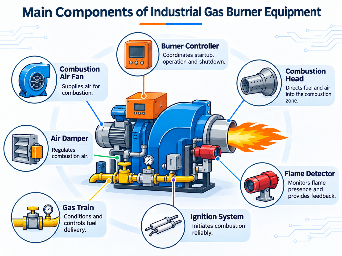
Gas burner equipment consists of interconnected mechanical, electrical, and control components that deliver fuel, supply combustion air, initiate ignition, and maintain controlled heat generation.
The exact configuration depends on the fuel type, required heating capacity, combustion chamber, and application.
Although designs vary, most industrial systems include several essential components.
| Component | Primary Function | Why It Matters |
Combustion head | Directs fuel and air into the combustion zone | Influences flame stability and combustion quality |
Combustion air fan | Supplies air for combustion | Supports the required airflow |
Air damper | Regulates combustion air | Helps maintain the intended air-fuel relationship |
Gas train | Conditions and controls fuel delivery | Supports stable and safe gas supply |
Ignition system | Initiates combustion | Enables reliable burner startup |
Flame detector | Monitors flame presence | Provides feedback for flame supervision |
Burner controller | Coordinates operating and safety sequences | Manages startup, operation, and shutdown |
Actuators | Position valves or dampers | Support staged or modulating operation |
These components must be compatible with one another. Replacing an individual device without considering the complete system can introduce operating or safety problems.
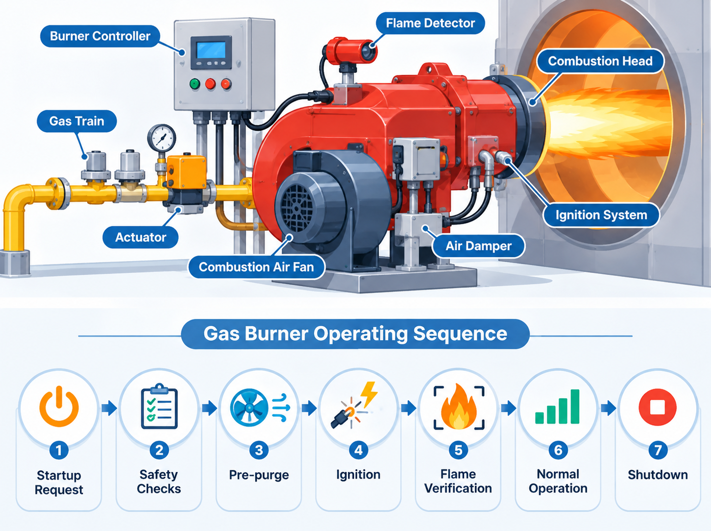
A typical automatic industrial gas burner follows a controlled startup and operating sequence.
Startup request: The control system receives a demand for heat.
Safety checks: Required permissive conditions and safety interlocks are verified.
Pre-purge: Where required, the combustion chamber is ventilated according to the approved sequence.
Ignition: The ignition system initiates combustion under controlled conditions.
Flame verification: The flame supervision system confirms successful ignition.
Normal operation: Fuel and air are regulated to meet heating demand.
Shutdown: Fuel supply is isolated through the specified control sequence.
The precise timing, valve operation, and safety logic depend on the burner design and applicable combustion safety requirements.
Industrial gas burners are used wherever a controlled heat source is required.
Typical applications include steam and hot-water boilers, industrial furnaces, drying equipment, process heaters, and thermal treatment systems.
A boiler burner may prioritize stable operation across changing heat demand. A furnace burner may require a particular flame shape or temperature distribution.
These differences influence burner selection, combustion head design, and control-system configuration.
The combustion head influences how fuel and air enter the combustion zone.
Depending on the burner design, components such as diffusers, nozzles, and swirlers help establish the intended flow pattern. Their geometry affects mixing, flame anchoring, and heat distribution.
Poorly matched components can cause unstable combustion even when gas pressure and airflow appear normal.
For this reason, combustion head selection must account for the fuel, burner firing rate, combustion chamber dimensions, and operating conditions.
Combustion problems often become visible through changes in flame behavior or exhaust conditions.
Flame instability: May result from unsuitable airflow, fuel pressure, or combustion head conditions.
Incomplete combustion: Can increase carbon monoxide formation and reduce combustion quality.
Soot accumulation: May indicate insufficient mixing or other combustion problems.
Flame lift-off: Can occur when flow conditions prevent the flame from remaining properly anchored.
Excessive emissions: May result from unsuitable operating conditions or incorrect equipment configuration.
These symptoms do not identify a single cause. Diagnosis requires appropriate measurements and inspection by qualified personnel.
Efficient combustion requires a suitable relationship between fuel flow, air supply, mixing, and flame temperature.
| Operating Factor | Possible Effect |
Insufficient combustion air | Increased risk of incomplete combustion and CO formation |
Excessive combustion air | Additional heat losses and reduced thermal efficiency |
Poor fuel-air mixing | Uneven combustion and unstable flame behavior |
High flame temperature | Can increase thermal NOx formation |
Incorrect burner adjustment | May affect efficiency, emissions, and operating stability |
Reducing emissions requires a balanced approach. Measures that reduce one pollutant may affect another, so combustion performance should be evaluated using appropriate instruments.
Gas burners can use different methods to supply combustion air.
| Feature | Natural Draft | Forced Draft |
Air movement | Driven primarily by pressure differences and buoyancy | Supplied by a fan or blower |
Main equipment | Draft path and suitable air openings | Fan, motor, damper, and associated controls |
Airflow control | Depends on system design and draft conditions | Can provide more direct airflow regulation |
Typical application | Suitable heating appliances and selected combustion systems | Many industrial boilers and process heating systems |
Main consideration | Dependence on available draft | Fan operation, power supply, and airflow verification |
Forced draft designs are widely used in industrial heating applications where controlled combustion air delivery is required.
Air dampers control the amount of air entering the burner.
In a simple system, damper position may be adjusted for a defined operating condition. More advanced burners use actuators to coordinate airflow with changing fuel demand.
For example, when a modulating burner increases its firing rate, the control system may reposition the air damper and fuel-control components according to an established operating curve.
Correct operation depends on the complete combustion control arrangement. Damper position alone does not establish whether the burner has the proper air-fuel ratio.
Combustion air equipment may include accessories that improve operating reliability.
Air filters: Help prevent airborne particles from entering sensitive components where filtration is required.
Silencers: Reduce noise generated by fans or airflow in suitable installations.
Fan assemblies: Deliver combustion air at the pressure and flow conditions required by the burner.
Airflow monitoring devices: Help verify that required combustion air conditions are present.
Inspection intervals depend on the environment. Dusty installations may require more frequent attention than clean indoor facilities.
The burner controller coordinates the operating sequence and responds to relevant safety signals.
Basic systems may operate at a fixed firing rate or use staged control. Modulating systems adjust burner output over a defined operating range.
The main operating modes can be compared as follows.
| Control Mode | Operating Principle | Common Consideration |
On/off | Burner operates at a defined firing rate or stops | Simple operation, possible cycling |
Two-stage | Burner switches between defined firing rates | Better output matching than basic on/off control |
Modulating | Burner output changes across an approved range | Greater flexibility under varying heat demand |
Modulating control can improve heat-demand matching, but actual energy savings depend on system design, operating conditions, and commissioning quality.
Actuators convert control signals into mechanical movement.
In industrial gas burner equipment, they may position air dampers or suitable fuel-control devices.
The operating arrangement can involve:
Electric actuators for controlled positioning
Pneumatic actuators in compatible industrial systems
Mechanical linkages that coordinate fuel and air movement
Actuator accuracy and repeatability influence how consistently the burner follows its established operating settings.
Incorrect positioning can disturb combustion. Adjustment and commissioning should therefore be performed by qualified technicians using approved procedures.
Flame supervision is a fundamental part of burner safety.
Depending on the application, systems may use ultraviolet sensors, infrared sensors, or flame ionization methods.
A flame detector provides information to the burner control system, which evaluates whether the required flame condition is present.
If flame failure occurs, the approved safety sequence must bring the burner to a safe state, including fuel isolation as required by the system design.
Buyers evaluating combustion monitoring components can also review this industrial flame detector for marine engine applications.
The detector must be compatible with the burner controller, fuel characteristics, and intended operating environment.
Industrial gas burners may use pressure switches and other protective devices to verify operating conditions.
Gas pressure switches monitor whether fuel pressure remains within the permitted range.
Air pressure switches help confirm suitable airflow conditions in systems that require them.
Temperature and process interlocks may prevent operation when specified limits are exceeded.
These devices form part of the overall safety arrangement. They should not be bypassed to keep a burner operating after a fault.
Industrial gas burners use different ignition arrangements according to their design and application.
| Ignition Method | How It Works | Key Consideration |
Direct spark ignition | An electrical spark ignites the main fuel-air mixture | Must be suitable for the burner and approved ignition sequence |
Interrupted pilot ignition | A pilot flame ignites the main burner and is then extinguished | Requires appropriate pilot supervision and control |
Intermittent or continuous pilot | A pilot remains available according to the system design | Fuel use and safety requirements depend on configuration |
Ignition transformers and electrodes must be matched to the burner.
Electrode condition, installation position, insulation, and wiring can all affect ignition reliability.
The gas train connects the fuel supply to the burner through a series of components.
A typical industrial arrangement may include:
Manual isolation valve → Gas filter → Pressure regulation → Safety shutoff valves → Burner fuel-control components
Additional pressure switches, valve proving devices, or other equipment may be required depending on the application.
The gas train must be designed for the fuel type, operating pressure, flow requirements, and applicable standards.
Component selection should not be based solely on pipe size.
Each gas train component has a specific function.
Gas filters remove suitable particulate contaminants that could affect downstream equipment.
Pressure regulators maintain the required downstream pressure within their specified operating conditions.
Safety shutoff valves isolate fuel flow when commanded by the safety control system.
Control valves regulate fuel delivery where the burner design requires variable output.
Relief devices, when used, perform a different protective function from automatic safety shutoff valves. They should not be treated as interchangeable.
A suitable burner must match the equipment it serves.
Before selecting a model, determine the heating duty, operating pattern, and installation conditions.
For a boiler, the required firing capacity and load variation are important. For a furnace, combustion chamber geometry and flame characteristics may have greater influence.
Fuel availability, gas pressure, and emission requirements must also be considered.
A structured specification sheet helps buyers compare models without overlooking important details.
| Specification | Questions to Ask |
Heat output | Does the burner meet the required heating capacity? |
Fuel compatibility | Is the equipment suitable for the available gas? |
Gas supply pressure | Does the burner match the supply conditions? |
Control method | Is on/off, staged, or modulating operation required? |
Electrical supply | Is the available voltage and frequency compatible? |
Combustion chamber | Is the burner suitable for the chamber geometry and pressure? |
Emissions | Can the system meet applicable requirements? |
Safety controls | Are the required interlocks and flame supervision functions provided? |
Installation dimensions | Will the equipment fit the mounting arrangement? |
Manufacturer specifications should be checked for the exact model rather than assumed from the product category.
Before requesting a quotation, prepare the application information.
A useful purchasing inquiry should explain the heating equipment, required thermal capacity, available fuel, gas pressure, electrical supply, and operating environment.
Buyers should also request technical drawings, control-system details, installation requirements, commissioning guidance, and information about spare parts.
For replacement projects, providing the existing burner model and relevant equipment documentation can help the supplier evaluate compatibility.
Gas burner problems can originate from several interconnected components.
| Symptom | Possible Areas to Investigate |
Burner fails to start | Power supply, controller status, safety interlocks |
Ignition failure | Ignition components, fuel supply, permitted startup conditions |
Repeated flame failure | Flame sensing, combustion stability, control-system faults |
Unstable flame | Fuel pressure, airflow, combustion head condition |
Increased fuel consumption | Operating settings, heat demand, system efficiency |
Excessive soot | Combustion quality, fuel characteristics, maintenance condition |
These are diagnostic categories, not instructions for adjusting safety-critical equipment.
Fault investigation should follow the manufacturer's documentation and be performed by qualified personnel.
Regular maintenance helps identify deterioration before it causes extended downtime.
Inspect the combustion head for deposits, damage, or abnormal wear.
Check fan operation and the condition of relevant air supply components.
Examine ignition electrodes, transformers, and associated wiring.
Verify flame supervision functions using approved testing procedures.
Inspect gas train components for signs of deterioration or leakage.
Check actuator operation and control-system fault records.
Maintain service records and replace components according to manufacturer requirements.
Maintenance frequency should reflect operating hours, environmental conditions, and the burner manufacturer's recommendations.
Certain symptoms require immediate attention.
Repeated ignition failures, unexplained flame loss, suspected gas leakage, damaged safety devices, or abnormal combustion behavior should not be ignored.
The burner should be placed in a safe condition according to the approved operating procedures, and qualified personnel should investigate the problem.
Safety interlocks must never be bypassed to restore operation.
Reliable gas burner performance depends on the complete combustion system, not simply the burner head or its rated heating capacity. Air supply, fuel regulation, ignition, flame supervision, and control components must operate together under the conditions for which the equipment was designed.
For industrial buyers, the most effective approach is to define the heating application first, then compare equipment specifications, control requirements, installation conditions, and maintenance needs. This helps avoid mismatched components and supports long-term operating reliability.
Shenzhen Zhongli Weiye Electromechanical Equipment Co., Ltd. provides gas burner equipment and related combustion products for industrial applications. Buyers can visit the company website to review available solutions and obtain further product information before selecting equipment for a specific project.
An industrial gas burner system typically includes a combustion head, air supply equipment, gas train, ignition system, flame detector, burner controller, and associated safety devices.
Natural draft systems rely on pressure differences to move combustion air, while forced draft systems use fans to supply air under controlled conditions.
The gas train conditions and controls fuel delivery through components such as filters, regulators, shutoff valves, and other devices required by the application.
A flame detector monitors a characteristic of the flame and provides a signal to the burner control system for flame supervision.
Possible causes include unsuitable airflow, fluctuating fuel pressure, combustion head problems, and incorrect operating conditions.
Maintenance intervals depend on operating hours, environmental conditions, equipment design, and the manufacturer's instructions.
Buyers should evaluate heat output, fuel compatibility, gas pressure, control method, combustion chamber requirements, safety functions, and installation conditions.