


A burner may have the correct heating capacity and a properly configured control system, yet still operate inefficiently because of problems at its fuel connections. Incorrectly sized fittings, incompatible sealing materials, or poorly supported pipework can affect fuel delivery, increase maintenance requirements, and create safety risks.
Burner fittings are essential connections within industrial combustion systems. Their installation requires careful attention to fuel compatibility, pressure ratings, connection methods, mechanical support, and applicable safety requirements.
This guide explains how to select and install burner fittings, what qualified technicians should verify during commissioning, and how routine maintenance supports reliable burner performance. It also examines common installation problems and their potential effects on combustion efficiency.
Understanding the Efficiency Role of Burner Fittings
What Are Burner Fittings?
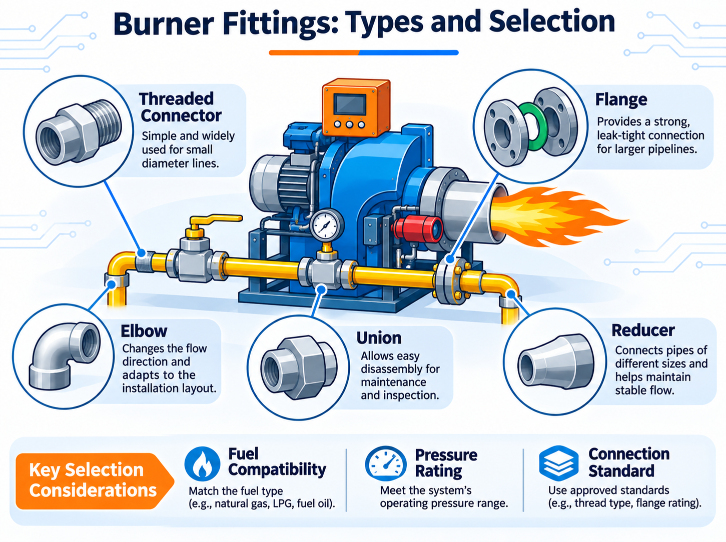
Burner fittings are components used to connect fuel supply lines, valves, regulators, and other equipment within a burner installation. Depending on the system, they may include threaded connectors, elbows, unions, reducers, flanges, and other approved connection components.
These fittings must maintain the required pressure integrity while allowing fuel to reach the burner under specified operating conditions.
In industrial gas burner systems, the arrangement of fittings and associated gas train components must be compatible with the burner's fuel demand, control requirements, and installation conditions.
How Burner Fittings Affect Combustion Efficiency
Burner fittings do not directly determine combustion efficiency. However, their dimensions, installation quality, and compatibility can influence the stability of fuel delivery.
| Installation Factor | Potential Effect | Performance Consideration |
|---|---|---|
| Incorrect fitting size | Excessive pressure loss or restricted flow | May limit available fuel delivery |
| Incompatible connection materials | Corrosion or material deterioration | May reduce connection reliability |
| Poor sealing | Fuel leakage | Creates safety risks and fuel losses |
| Unsupported pipework | Mechanical stress on connections | May contribute to premature damage |
| Unsuitable fitting arrangement | Additional flow resistance | May affect pressure conditions at the burner |
Stable fuel delivery is one of several conditions required for effective combustion. Air supply, burner adjustment, heat demand, and combustion chamber design must also be considered.
The Relationship Between Fittings and Fuel Pressure
Fuel pressure can change as gas or liquid passes through pipes, valves, and fittings. Every component introduces some degree of flow resistance.
In a properly engineered system, the combined pressure losses remain within the allowable limits for the burner and associated equipment.
Problems can occur when fittings are undersized, unnecessary restrictions are introduced, or the installation differs significantly from the approved design.
For this reason, fitting selection should be based on calculated flow requirements and the manufacturer's technical specifications rather than connection diameter alone.
Pre-Installation Assessment: Preparing for the Right Burner Fittings
Review Fuel Type and Operating Conditions
Before installing burner fittings, technicians must identify the fuel and the operating conditions of the system.
Natural gas, LPG, and liquid fuels have different physical properties and may require different connection materials, sealing methods, and component approvals.
The pre-installation assessment should establish:
Fuel type: Natural gas, LPG, fuel oil, or another approved fuel.
Operating pressure: Expected minimum and maximum pressure conditions.
Flow requirements: Fuel demand at the specified burner operating range.
Temperature: Expected ambient and component operating temperatures.
Installation environment: Exposure to moisture, corrosion, vibration, or mechanical stress.
Applicable requirements: Relevant codes, equipment approvals, and manufacturer instructions.
These conditions determine which fittings can be safely incorporated into the installation.
Inspect Existing Connections and Pipework
For retrofit or replacement projects, the condition of existing equipment requires particular attention.
Corrosion, damaged threads, distorted flanges, and poorly supported piping may indicate that replacing an individual fitting will not resolve the underlying problem.
Technicians should also confirm that existing connections match the replacement components. Similar-looking fittings may use different thread forms, sealing arrangements, or pressure classifications.
Forcing incompatible connections together can damage components and compromise joint integrity.
Pre-Installation Inspection Checklist
| Inspection Item | Required Verification |
|---|---|
| Burner documentation | Installation drawings and manufacturer requirements are available |
| Connection dimensions | Fitting sizes and connection standards match the approved design |
| Component condition | No visible damage, corrosion, or manufacturing defects |
| Material compatibility | Fittings and seals are suitable for the specified fuel |
| Pressure rating | Components are approved for the expected operating conditions |
| Mechanical support | Pipework does not impose unacceptable loads on burner connections |
Any discrepancy should be resolved before installation proceeds.
Selecting Burner Fittings Designed for Optimal Performance
Comparison of Common Burner Fitting Materials
Material selection depends on fuel compatibility, pressure, temperature, corrosion exposure, and applicable connection standards.
| Material | Common Advantages | Selection Considerations |
|---|---|---|
| Stainless Steel | Good corrosion resistance and mechanical durability | Grade, pressure rating, temperature, and fuel compatibility must be verified |
| Brass | Good machinability and suitability for certain approved gas connections | Not suitable for every fuel, environment, or temperature range |
| Carbon Steel | Mechanical strength and broad industrial availability | Corrosion protection may be necessary |
| Aluminum | Low weight and useful properties in selected applications | Requires specific approval for the intended pressure and fuel service |
No material is universally suitable for every burner installation. The approved component specification should take precedence over general material comparisons.
Threaded, Flanged, and Other Connection Types
Burner installations may use different connection methods depending on equipment size, operating conditions, and applicable standards.
Threaded connections are used in certain approved piping arrangements and require compatible thread forms and sealing methods.
Flanged connections are common where larger components or removable equipment assemblies must be joined. Their integrity depends on compatible flanges, gaskets, fasteners, and approved assembly procedures.
Welded connections may be specified for particular permanent piping arrangements and require qualified personnel and appropriate inspection.
The connection method should be determined by the engineered system design, not simply by installation convenience.
How to Avoid Incorrect Fitting Selection
Several purchasing mistakes can introduce unnecessary installation problems.
Choosing fittings based only on nominal pipe diameter.
Assuming all thread standards are interchangeable.
Using seals without verifying fuel compatibility.
Ignoring maximum pressure and temperature ratings.
Replacing approved components with visually similar alternatives.
Technical documentation and component traceability are particularly important for industrial fuel systems.
Step-by-Step Installation Process for Burner Fittings
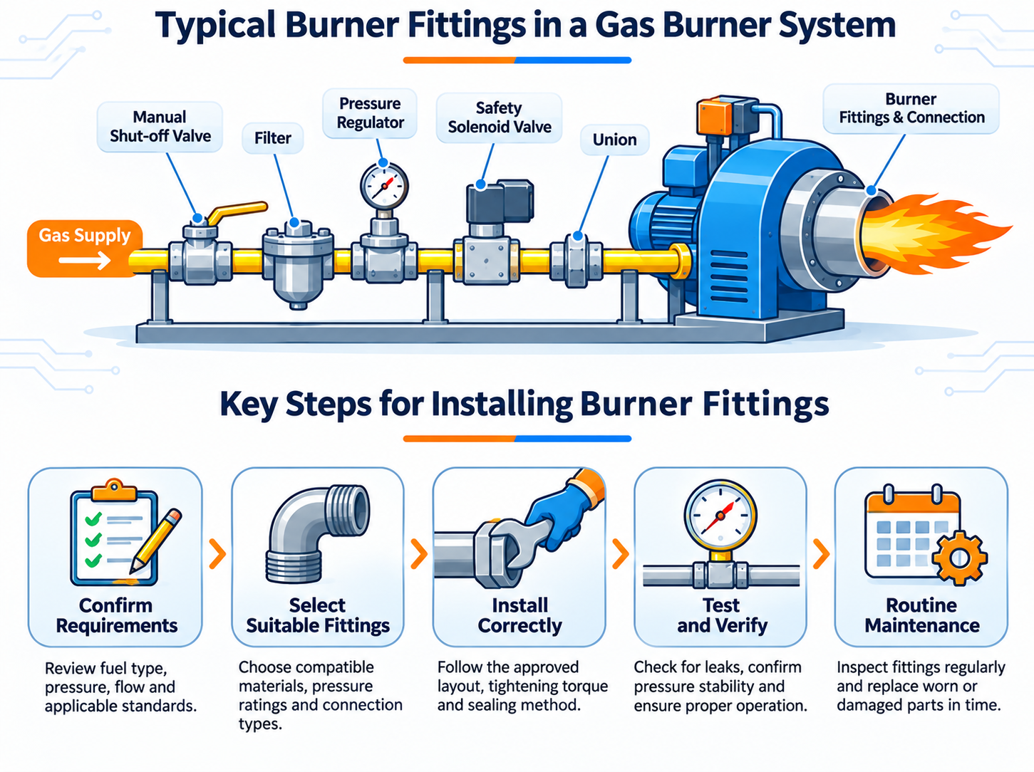
Installation of fuel-carrying burner fittings must be performed by qualified personnel under the applicable codes, approved engineering documentation, and manufacturer instructions.
The following workflow describes the principal installation stages and verification requirements rather than a substitute for a certified installation procedure.
Step 1: Establish Safe Working Conditions
Before work begins, the responsible personnel must implement the required isolation and lockout procedures.
The installation should be confirmed safe for maintenance according to the facility's approved procedures. Relevant hazards include residual pressure, combustible atmospheres, electrical energy, and hot equipment surfaces.
Work must not begin until the required safety conditions have been established.
Step 2: Verify Component Compatibility
Each fitting should be checked against the approved installation documentation before assembly.
This includes verifying the connection type, dimensions, material, pressure rating, and intended service.
Damaged or unidentified components should not be installed in a fuel system.
Step 3: Assemble Connections According to Approved Procedures
Qualified installers should use the connection methods, sealing products, tightening requirements, and assembly sequence specified for the equipment.
Not every connection requires thread sealant. Some joints rely on gaskets, mechanical sealing surfaces, or other engineered arrangements.
Using an unsuitable sealant or applying it incorrectly can compromise sealing performance or introduce contamination into downstream components.
Step 4: Verify Mechanical Alignment and Support
After assembly, the installation must be checked for mechanical stress, unsupported loads, and interference with adjacent equipment.
Pipework should not force burner connections out of their intended position.
Appropriate supports and allowances for thermal movement are important where required by the piping design.
Step 5: Complete Inspection and Approved Testing
Before the burner is returned to service, qualified personnel must complete the required pressure integrity, leak-tightness, and functional verification procedures.
Test methods, test media, pressures, acceptance criteria, and isolation arrangements must follow the applicable codes and approved documentation.
The burner should not be operated until the required inspections and safety checks have been completed successfully.
Ensuring Proper Alignment, Calibration, and Sealing
Why Mechanical Alignment Matters
Correct alignment helps prevent unwanted mechanical loads on fittings, valves, and burner connections.
Misalignment may occur when piping is installed without adequate support or when replacement components have different dimensions from the original equipment.
Over time, vibration and thermal movement can increase stress at poorly supported joints.
Mechanical alignment should therefore be checked as part of the complete installation rather than treated as an isolated adjustment.
Common Installation Problems and Their Effects
| Observed Problem | Possible Cause | Potential Consequence |
|---|---|---|
| Repeated connection leakage | Incorrect joint assembly, damaged sealing surfaces, or incompatible components | Safety risk and equipment downtime |
| Unexpected pressure loss | Restricted flow path, incorrect sizing, or upstream system problems | Insufficient fuel pressure at the burner |
| Connection deformation | Mechanical stress or unsuitable assembly practices | Reduced joint integrity |
| Corrosion around fittings | Environmental exposure or material incompatibility | Potential deterioration and maintenance requirements |
| Unstable burner operation | Fuel supply, airflow, control, or combustion-related faults | Possible efficiency and reliability problems |
These symptoms may have multiple causes. Troubleshooting should consider the complete burner system rather than assuming that every combustion problem originates from a fitting.
Combustion Calibration After Installation
Fittings themselves are generally not calibrated in the same way as regulators, actuators, or burner control equipment.
However, changes to the fuel supply arrangement may require qualified technicians to verify burner operating conditions during commissioning.
Depending on the system, this may involve checking fuel pressure, combustion air conditions, flame stability, and exhaust gas measurements.
Industrial burner efficiency depends on maintaining the required combustion conditions across the intended operating range.
Where appropriate, combustion analysis can help identify excessive oxygen, incomplete combustion, or other conditions affecting performance.
Safety, Compliance, and Performance Verification
Applicable Installation and Safety Requirements
Burner fitting installations must comply with the requirements applicable to the fuel, equipment, installation location, and jurisdiction.
These may include fuel gas codes, industrial combustion safety standards, pressure equipment requirements, and manufacturer instructions.
In certain applications, standards such as NFPA 54, NFPA 85, or NFPA 86 may be relevant within their respective scopes.
Not every standard applies to every burner. The responsible engineer or qualified installer must determine the correct requirements for the specific system.
Performance Verification Before Operation
Following installation, commissioning should confirm that the system operates as intended.
Connection integrity: Required inspections and leak-tightness tests have been completed.
Fuel delivery: Pressure and flow conditions meet the approved equipment requirements.
Safety controls: Relevant interlocks and protective functions have been verified.
Combustion performance: Burner operation has been evaluated using appropriate procedures and instruments.
Documentation: Test results, deviations, and corrective actions have been recorded.
Any unresolved safety-related fault must be addressed before the system is released for operation.
Integrating Burner Fittings With Combustion Controls
Fuel fittings form part of a wider assembly that may include filters, pressure regulators, safety shutoff valves, and control devices.
These components must operate together to maintain the conditions required by the burner.
For example, a fuel delivery problem may affect ignition reliability or flame stability. The burner's flame supervision system must respond according to the approved safety sequence.
In applications using specialized flame detection equipment for marine engines, compatibility with the combustion control system is particularly important.
Mechanical fuel connections and electronic safety functions should therefore be evaluated as parts of the same installation.
Long-Term Maintenance Strategies to Preserve Efficiency
Routine Inspection of Burner Fittings
Burner fittings may be exposed to vibration, temperature changes, moisture, and other operating stresses.
Scheduled inspections help identify deterioration before it develops into a more serious problem.
Maintenance personnel should examine accessible connections for corrosion, physical damage, unsupported pipework, and other visible abnormalities.
Any suspected leakage must be handled according to the facility's approved safety procedures.
Preventive Maintenance Checklist
| Maintenance Task | Purpose |
|---|---|
| Inspect fittings and connections | Identify visible damage or deterioration |
| Check piping supports | Identify mechanical stress and movement |
| Review operating pressure records | Detect abnormal changes in fuel delivery conditions |
| Inspect associated valves and regulators | Identify issues affecting fuel system performance |
| Complete required integrity testing | Verify connection condition under approved procedures |
| Maintain inspection records | Support maintenance planning and equipment history |
Inspection intervals should be determined by manufacturer recommendations, operating conditions, applicable requirements, and the site's maintenance program.
When Should Burner Fittings Be Replaced?
Replacement may be necessary when fittings show damage, unacceptable corrosion, deformation, or other conditions that compromise their suitability for service.
Components should also be replaced when they no longer meet the system's approved specifications.
Reusing a fitting after disassembly depends on its design, condition, and manufacturer instructions. Some seals and connection components are intended for single use.
Replacement decisions should be based on documented technical requirements rather than appearance alone.
Conclusion
Efficient burner operation depends on more than combustion settings and equipment capacity. Properly selected and installed burner fittings help maintain the integrity of the fuel delivery system and support the stable operating conditions required for reliable combustion.
The installation process should begin with a review of fuel characteristics, connection requirements, pressure ratings, and environmental conditions. Qualified assembly, approved testing, commissioning, and preventive maintenance are equally important for long-term performance.
Shenzhen Zhongli Weiye Electromechanical Equipment Co., Ltd. supplies industrial burner equipment and related combustion components. Matching burner fittings with the requirements of the complete combustion system is an important consideration when selecting equipment for new installations, maintenance projects, and system upgrades.
FAQ
Why are burner fittings important for combustion efficiency?
Correctly selected burner fittings support stable fuel delivery, reduce avoidable pressure losses, and help maintain the connection integrity required for reliable burner operation.
What materials are commonly used for burner fittings?
Common materials include stainless steel, brass, and carbon steel, but the appropriate choice depends on fuel compatibility, operating pressure, temperature, and applicable standards.
How often should burner fittings be inspected?
Inspection intervals depend on manufacturer instructions, operating conditions, applicable safety requirements, and the facility's maintenance program.
Can incorrect burner fittings cause fuel leakage?
Yes, incompatible components, damaged connections, unsuitable seals, and incorrect assembly can compromise joint integrity and create fuel leakage risks.
What sealant should be used for burner fittings?
The sealing method must be approved for the specific connection, fuel, pressure, and temperature conditions, and some fittings use gaskets or engineered sealing surfaces rather than thread sealants.
Can burner fittings affect flame stability?
Incorrectly sized or restricted fittings may affect fuel pressure and flow, potentially contributing to unstable combustion when other operating conditions are also considered.
Should damaged burner fittings be repaired or replaced?
Damaged fittings should be assessed by qualified personnel and replaced when required by manufacturer instructions, applicable standards, or the approved maintenance procedure.