lucy@zlwyindustry.com
+86-158-1688-2025
Please Choose Your Language
- All
- Product Name
- Product Keyword
- Product Model
- Product Summary
- Product Description
- Multi Field Search

Views: 0 Author: Site Editor Publish Time: 2026-11-03 Origin: Site


Frame the decision around operational goals. Are you trying to sustain a steady, continuous flame within a heat exchanger? Or are you moving bulk fluids between primary and secondary storage tanks? Setting clear baseline success criteria helps you avoid fundamental design flaws. You must align the mechanical capabilities of the pump with the fluid's ultimate destination. An application requiring continuous circulation demands vastly different engineering than an application needing intermittent, high-volume evacuation. Facilities often face systemic failures simply because designers misunderstood the primary operational goal. We must separate the concept of moving fluid from the concept of preparing fluid for combustion.
Heating systems require precise pressure regulation to function safely and efficiently. Most modern commercial and residential burners operate between 100 and 300 PSI. Standard transfer pumps simply cannot safely maintain this delicate micro-pressure window. They lack the sophisticated internal regulating valves necessary to push fuel through a tiny, precisely machined nozzle orifice. Burner Oil Pumps handle this atomization requirement seamlessly. They compress the fluid until it bursts into a fine, highly combustible mist. Without this extreme pressure, the oil will merely dribble out of the nozzle. This results in incomplete combustion, heavy soot accumulation, and eventual system failure. Atomization dictates that pressure always takes precedence over volume.
Facilities often face severe geographical challenges regarding fuel storage. Your primary combustion pump might struggle to pull fuel from an underground storage tank buried several feet below grade. Distant exterior tanks create similar, frustrating suction problems due to horizontal pipe friction. When the total vacuum resistance exceeds the mechanical limits of the primary pump, you face immediate fuel starvation. The internal gears cannot generate enough suction to overcome the physical weight of the fluid column. These scenarios necessitate an auxiliary pumping solution to bridge the gap. You must install a mechanism that pushes the fluid toward the appliance, overcoming the physics of gravity and distance.
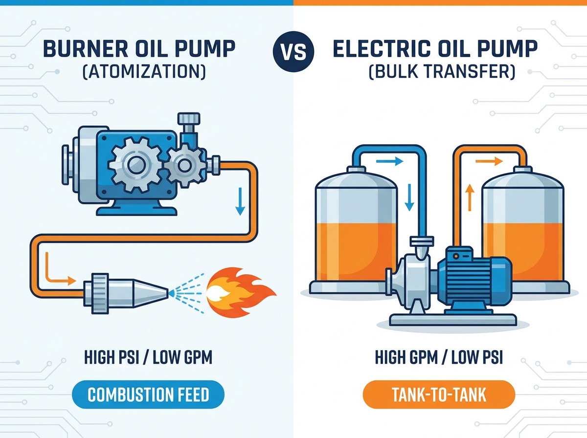
These units function as high-precision mechanical instruments rather than simple fluid movers. They operate primarily as rotary gear pumps mechanically coupled directly to the burner fan motor. As the appliance motor spins—typically at 1725 or 3450 RPM—it simultaneously drives the blower fan and the internal pump gears. This synchronized rotation draws fuel into the gear cavity and pressurizes it against the regulating valve. The mechanical coupling ensures fluid delivery remains perfectly timed with the combustion air supply.
They feature intricate, built-in pressure regulation valves. You get ultra-precise flow control tailored specifically to the exact nozzle capacity required by the heating appliance. Furthermore, they offer inherently fail-safe integration. If the primary burner motor stops due to a power failure or a safety limit trip, fuel delivery halts instantly. This mechanical interlock provides a critical safety barrier against unburned fuel pooling inside the combustion chamber. They also feature internal bypass capabilities. This allows excess fluid to return to the tank or circulate internally without damaging the delicate shaft seals.
Despite their precision, they suffer from exceptionally poor dry-lift capabilities. They prove highly sensitive to microscopic air leaks in the suction line. A tiny leak can easily break the vacuum and cause a total loss of prime. High-viscosity or extremely cold oils can quickly overwhelm their small internal gear sets, causing the motor to stall or the coupling to shear. You must actively avoid subjecting them to excessive vacuum pressure. Industry best practices suggest keeping suction resistance well below 10 to 15 inches of mercury.
These pumps utilize completely independent motor operation. You can power them via standard AC circuits for permanent installations or DC batteries for mobile applications. Engineers design them specifically for either continuous circulation or intermittent, rapid fluid transfer duties. They operate completely decoupled from the primary heating appliance, relying on their own internal impellers, vanes, or heavy-duty gears to move the liquid.
They boast massive displacement capabilities. Manufacturers measure their output in gallons per minute rather than gallons per hour. They excel at pushing high-viscosity fluids like heavy gear lubricants, synthetic blends, or thick waste oil. Portability remains a key advantage for mobile fuel polishing, fleet servicing, or emergency tank evacuation. They can push dense fluids over incredibly long distances effortlessly. This makes them ideal for feeding pressurized loop systems in sprawling commercial facilities.
However, you must provide dedicated electrical infrastructure to run them. This includes installing proper breakers, wiring runs, and control relays. They lack inherent designs to regulate the micro-pressures needed for sensitive combustion nozzles. Pushing fuel directly into a combustion chamber using a high-volume transfer pump risks severe over-pressurization. They absolutely require external safety interlocks to ensure they shut down if the primary heating appliance fails.
When comparing options for your facility, you must systematically evaluate several critical engineering dimensions. Ignoring these factors inevitably leads to premature equipment failure.
You must carefully compare the inverse relationship between pressure and flow rate. Burner Oil Pumps strictly prioritize high PSI to force liquid through restrictive nozzles. Their total flow rate remains quite low, often measured in fractions of a gallon per hour. Conversely, standalone electric pumps prioritize high GPM to evacuate tanks rapidly or fill day-tanks efficiently. You cannot easily swap one function for the other. High pressure requires tight gear tolerances. High volume requires significantly larger displacement chambers.
Evaluate how each unit handles cold-weather fluid thickening. As ambient temperatures drop, heating oil and diesel become sluggish, sharply increasing their kinematic viscosity. Dedicated electric pumps utilize higher torque motors and larger internal clearances. They handle heavy and waste oils significantly better during harsh winter months. Mechanical gear pumps, with their tight microscopic clearances, often struggle to process thickened fuel. This frequently leads to blown shaft seals or sheared drive couplings.
Consider the physical layout and constraints of your mechanical room. Motor-mounted integrated units save significant space. They draw power directly from the existing appliance circuit, requiring no additional wiring runs. Standalone electric units demand a dedicated physical footprint, often requiring heavy-duty wall brackets or floor mounts. You also need separate wiring requirements, typically 120V or 240V dedicated circuits, along with specialized motor starters.
Highlight necessary regulatory certifications before making a final selection. You must verify UL listings specific to the exact fluid you intend to pump. Indoor oil storage and transfer often require strict NFPA 31 compliance. Industrial environments, chemical plants, or mining operations might demand ATEX or Explosion-proof ratings for any standalone electrical equipment. Integrated pumps generally fall under the overarching certification of the tested heating appliance itself.
Technical Specifications Comparison
| Evaluation Criteria | Mechanical/Integrated Units | Standalone Electric Units |
|---|---|---|
| Primary Application | High-pressure atomization, direct combustion feed. | High-volume transfer, day-tank filling, loop systems. |
| Pressure/Volume Focus | High PSI (100-300+), Low GPH. | Low to Medium PSI, High GPM. |
| Viscosity Tolerance | Low to Moderate (Highly sensitive to cold oil). | High (Excellent for heavy waste oils and lubricants). |
| Power Source | Mechanically driven by the appliance fan motor. | Independent AC/DC electrical circuits. |
| Safety Integration | Inherently fail-safe; stops when appliance stops. | Requires external relays and safety interlocks. |
You face severe mechanical risks if you inadvertently starve a primary pump of fluid. If the suction line runs too long, or if the pipe diameter is too small, the vacuum pressure spikes dramatically. This extreme vacuum causes the liquid fuel to vaporize inside the pipe, creating dangerous cavitation bubbles. When these bubbles enter the pressurized gear cavity, they implode with immense force. This action pits the metal gears and destroys the pump. Adding an electric boost supply pump might seem logical to overcome this vacuum. However, it requires exceptionally careful pressure regulation. If the supply pressure from the transfer pump exceeds the primary pump's maximum inlet rating, you risk catastrophic seal blowout and massive fuel leaks.
High-speed electric transfer pumps operate aggressively and move large volumes of fluid rapidly. They can easily push accumulated dirt and debris straight through standard filtration media. This high-velocity flow forces microscopic particulates past the filter element by distorting the paper or synthetic mesh. If you do not stage your filtration properly—using step-down micron ratings and oversized housings to slow the fluid velocity—this bypassed debris inevitably clogs downstream burner equipment. A clogged nozzle immediately disrupts the atomization pattern, leading to erratic flames and dangerous soot buildup.
Every mechanical component in a fluid delivery system requires routine service and inspection. Replacing integrated strainers proves relatively simple, clean, and requires minimal operational downtime. Servicing standalone electric motors, replacing worn carbon brushes, and swapping out damaged impellers demands significantly more physical labor and expertise. You must regularly inspect external shaft seals on standalone units to prevent environmental contamination. Ignoring these maintenance realities compromises the safety and reliability of your entire fuel handling infrastructure.
Use the following structured approach to select the correct equipment for your facility. Bypassing these steps often leads to mismatched equipment and operational failures.
The choice between these two pump architectures is rarely a simple decision based on personal preference. It remains a strict, unforgiving engineering requirement dictated entirely by the fluid's final destination. High-pressure atomization absolutely demands specialized, integrated regulating equipment designed specifically for combustion. Conversely, high-volume bulk transfer requires robust, independent motor power capable of overcoming distance and viscosity challenges.
We always recommend consulting a certified HVAC technician or specialized fluid handling engineer. They should thoroughly audit your piping geometry, lift parameters, and pressure requirements. Doing so ensures you finalize a safe, appropriate purchase and helps you avoid dangerous, ad-hoc modifications to an existing fuel delivery loop. Validate your specific lift requirements, calculate your total friction loss, and verify all safety certifications before altering your facility's critical infrastructure.
A: Generally no. Standard transfer pumps output massive volume but completely lack the precision micro-pressure regulation needed for atomization. You can only utilize them if specifically configured as part of a regulated day-tank or a specialized pressurized loop system. Connecting a transfer pump directly causes severe pressure mismatches at the nozzle. This invariably leads to immediate system lockouts, incomplete combustion, or dangerous unburned fuel pooling within the combustion chamber.
A: Losing prime almost always indicates a vacuum disruption within the suction line. Common causes include microscopic air leaks at pipe flared fittings, failing check valves, or a severely clogged internal strainer. Additionally, if the vertical lift requirement exceeds the pump’s mechanical rating—often drawing more than 15 inches of mercury—the internal gears will struggle to maintain suction. The fluid column drops back into the tank, causing the unit to lose its prime.
A: They are only safe if specifically engineered and rated for hazardous, volatile environments. You must ensure the chosen unit features fully enclosed, explosion-proof motors and proper safety bypass valves. Always scrutinize the manufacturer specifications regarding specific fluid flash points and allowable operating temperatures. Using a standard, unrated transfer pump for highly volatile fluids violates safety codes and poses a severe, immediate fire hazard.