lucy@zlwyindustry.com
+86-158-1688-2025
Please Choose Your Language
- All
- Product Name
- Product Keyword
- Product Model
- Product Summary
- Product Description
- Multi Field Search

Views: 0 Author: Site Editor Publish Time: 2026-11-14 Origin: Site


Industrial and high-risk environments demand uncompromising fire safety protocols. You need fire detection systems capable of reacting in milliseconds. Modern manufacturing and chemical processing have evolved, creating faster and more volatile production cycles. These advanced systems must trigger long before traditional smoke or heat sensors even register a threat. Selecting the wrong sensor often leads to two costly extremes. You either suffer from nuisance tripping, where false alarms needlessly halt production, or you fail entirely to detect specific chemical fires. Both scenarios carry immense physical and operational risks.
This article provides facility managers, safety engineers, and procurement teams a clear framework for evaluating Flame Detectors. We will explore how to align these critical devices based on specific fuel types and harsh environmental conditions. You will also learn how to prioritize essential compliance specifications to ensure reliable, life-saving performance across your entire facility.
Traditional smoke and heat detectors depend on the physical transport of combustion products. Smoke must physically drift upward through the air to reach a ceiling-mounted unit. Heat must rise sufficiently to trigger a thermal element. This older methodology operates far too slowly for hazardous environments. In highly volatile areas like petrochemical plants, chemical storage bunkers, or aircraft hangars, you simply cannot wait minutes for smoke to travel. A rapidly expanding fire can consume an entire production zone in seconds. This urgent business problem necessitates an immediate, line-of-sight solution that sees the fire the moment ignition occurs.
Success criteria for a modern hazard environment demand much more robust capabilities. A viable optical sensor must deliver sub-second response times upon ignition. It must also maintain an exceptionally high Mean Time Between Failures (MTBF) under exceedingly harsh conditions. Facilities face a severe operational penalty if they deploy inadequate sensors. A false fire-suppression dump, such as unintentionally triggering a massive deluge system or a chemical clean agent release, causes massive operational downtime. Your facility must halt all work, clean up the suppression agents, and reset the entire safety matrix. You must balance the implementation of advanced optical sensors against the catastrophic risk of these unwarranted system activations. If a sensor triggers due to a harmless reflection, the resulting production halt destroys operational efficiency and wastes valuable resources.
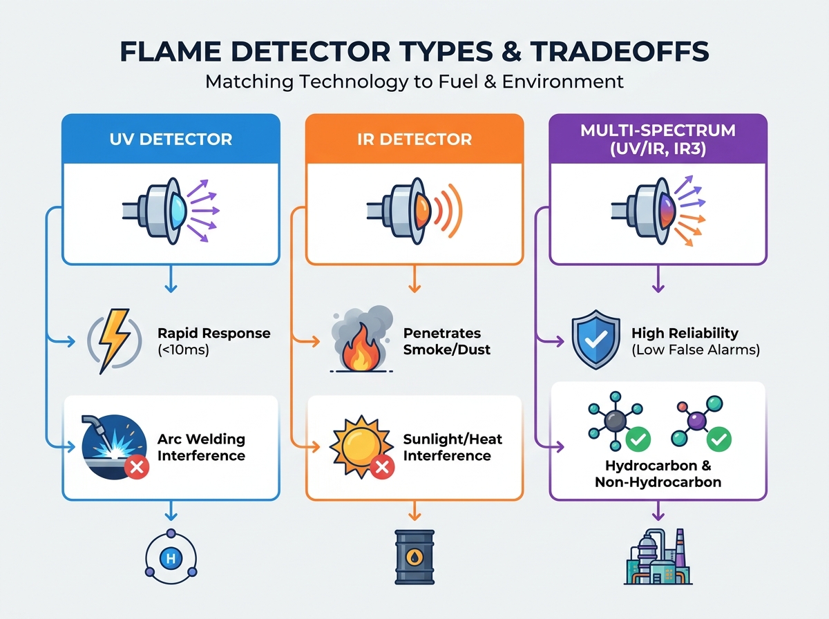
Optical Sensor Technology Comparison
| Technology Type | Spectral Range | Ideal Environments | Primary Limitations |
|---|---|---|---|
| Ultraviolet (UV) | 0.18 to 0.26 microns | Clean facilities, non-hydrocarbon fuel hazards | Arc welding interference, oil mist blindness |
| Infrared (IR) | 4.3 or 4.4 microns | Dusty or smoky industrial environments | Blackbody radiation, water and ice buildup |
| Multi-Spectrum (IR3) | Three distinct IR bands | Complex petrochemical and outdoor spaces | Requires strict line-of-sight mapping |
UV technology detects radiation in the 0.18 to 0.26 micron range. This specific spectrum makes them highly sensitive to both hydrocarbon and non-hydrocarbon fires. Their rapid response time often registers under 10 milliseconds. This blazing speed serves perfectly for specialized, pristine applications such as munitions manufacturing or advanced cleanrooms. However, UV sensors possess major operational limitations. They are highly susceptible to false alarms from nearby arc welding, sudden lightning strikes, and unshielded halogen lamps. Furthermore, you should avoid installing them in environments prone to heavy airborne oil mist or thick smoke. These physical contaminants easily absorb and block UV radiation, effectively blinding the sensor when you need it most.
Single-frequency IR devices typically monitor the 4.3 or 4.4 micron range. This specific band represents the exact CO2 emission peak generated by burning hydrocarbon fires. IR sensors excel in inherently dirty environments. Infrared wavelengths penetrate thick smoke and heavy dust far better than UV waves. But IR technology is not flawless. It remains highly vulnerable to blackbody radiation interference. Hot machinery, industrial ovens, or intense sunlight reflections can trick the sensor into falsely reporting a fire. Additionally, harsh weather factors severely degrade IR transmission. Water, ice, and heavy condensation on the outer lens will compromise the unit's ability to see an actual hazard.
Multi-spectrum devices combine varied technologies to overcome individual sensor weaknesses. UV/IR units require both ultraviolet and infrared thresholds to trigger simultaneously. The internal logic triggers an alarm only when both unique signatures exist in the viewing area. This dual-validation drastically reduces false alarms compared to standalone UV or IR sensors.
Triple IR (IR3) technology represents an even more advanced approach. It utilizes three specific infrared bands to verify a threat. This isolates the unique flicker frequency and exact spectral signature of a live fire. It simultaneously filters out persistent background radiation. IR3 currently stands as the baseline for complex petrochemical deployments. It offers an optimal balance of extended range, often reaching up to 200 feet, and the highest possible false alarm immunity in modern hazard detection.
Different fuels burn in entirely different ways. Hydrocarbons like wood, paper, oil, gas, and standard plastics emit strong CO2 peaks upon combustion. Because of these distinct carbon-based emissions, you must monitor them using IR3 or UV/IR sensors. These units specifically seek out the 4.3-micron signature to verify ignition.
Non-hydrocarbons behave completely differently. Hydrogen, ammonia, and certain combustible metals do not emit CO2 as a byproduct when they ignite. If you deploy a standard IR sensor looking for a CO2 peak, it will completely fail to see a roaring hydrogen fire. For these invisible hazards, you must use UV sensors. Alternatively, you can deploy specific multi-spectrum sensors precisely calibrated for water-band emissions. Understanding your primary fuel source remains a foundational step in proper risk mitigation and ensuring system efficacy.
Your physical location heavily dictates hardware requirements. Indoor deployments in confined spaces typically require wider Fields of View (FoV). You must also carefully profile the ambient background radiation from surrounding manufacturing equipment. Ovens, massive combustion engines, or uninsulated hot pipes can easily trigger poorly calibrated units indoors.
Outdoor considerations pose much more aggressive challenges. Sunlight immunity is absolutely non-negotiable for outdoor sensors. Direct and reflected solar radiation will overwhelm basic IR units. Furthermore, exterior detectors must withstand brutal weather patterns. You must shield them from heavy rain, corrosive salt fog, and thick snow accumulation. Extreme temperature fluctuations often necessitate units equipped with internally heated optics. These internal heaters prevent dangerous ice formation across the viewing window, ensuring constant vigilance.
When comparing various models, procurement teams should focus strictly on hard data rather than generic marketing terminology. You must verify actual performance metrics to protect your facility.
You must deeply analyze these critical specifications:
Do not accept maximum range claims at face value. You must evaluate the stated range against a specific, standardized fire size. For example, a manufacturer might claim a 150-foot detection range. You need to know if that specification applies to a massive, uncontrolled blaze or a standard 1x1 foot n-heptane pan fire. Always demand the pan fire metric for accurate comparisons.
The standard FoV for most optical sensors typically spans 90° to 120°. A wider FoV reduces the total number of Flame Detectors you need to cover a room. However, expanding the viewing angle often sacrifices long-distance sensitivity at the far edges of the viewing cone.
Nuisance alarms destroy operational efficiency and breed complacency among safety personnel. Review the manufacturer’s rigorous testing data for specific nuisance sources prevalent in your facility. Look closely at how the device handles nearby arc welding, heavy industrial grinders, direct sunlight, reflected sunlight, and blackbody heaters. Ensure the unit actively suppresses alarms when exposed to these specific environmental triggers.
Industrial safety relies entirely on independent validation. You cannot trust unverified metrics for life-safety equipment.
Optical detectors act exactly like cameras; they require a perfectly clear, unobstructed line of sight. Physical obstacles easily block their view. Scaffolding, large transport vehicles, or temporary maintenance equipment can create extremely dangerous blind spots. To avoid these severe coverage gaps, engineers require strict 3D mapping during the design phase. Fire and gas (F&G) mapping software simulates the exact FoV of each individual sensor. This digital validation ensures comprehensive coverage overlaps and guarantees no critical area remains unprotected.
Even the most advanced sensor fails if its external lenses are dirty. Lenses will naturally accumulate airborne dirt, oil mist, and salt spray over time. A must-have feature for any industrial deployment is Continuous Optical Ring Integrity. This automatic self-testing mechanism continuously monitors the transparency of the lens surface. It typically bounces an internal IR signal off the outer window. It immediately alerts the main control panel if the lens becomes obscured by grime or physical blockages, prompting immediate maintenance.
Routine maintenance must remain straightforward and safe. Assess the availability of compatible test lamps for periodic maintenance checks. Determine if testing the unit requires a technician to physically intrude into the hazardous area via scaffolding. Many modern devices support remote diagnostics via HART or RS-485 protocols. This advanced connectivity allows your maintenance team to monitor sensor health, adjust sensitivity, and run diagnostic checks directly from the safety of the main control room, drastically reducing maintenance hazards.
A: Expect an operational lifespan of 10 to 15 years. This longevity heavily depends on environmental exposure. Adherence to strict maintenance schedules also plays a major role in keeping the unit functional.
A: Standard window glass blocks UV radiation and severely attenuates specific IR bands. The line-of-sight must be direct. Placing standard glass between the sensor and the hazard will cause the device to fail.
A: Thermal cameras are excellent for pre-ignition hot-spot detection. However, standard optical detectors are faster at identifying actual ignition. They also carry specific life-safety certifications required by most regulatory bodies.
A: Most regulatory bodies, such as NFPA, require functional testing at least annually. Facilities perform this using specialized manufacturer test lamps. This manual testing is supplemented by the device's own continuous self-diagnostics.